Split Marking
Split Marking enables the ability to mark designs larger than a Galvo laser's work area using a Rotating or Linear axis table.
By specifying a Split Size, you can tell LightBurn to divide your design into segments, then mark individual segments between movements of the external axis, continuing until the entire design has been marked.
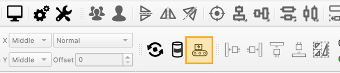
To configure your external axis' motion parameters and enable the Split Marking tool, click the conveyor icon in the Modes Toolbar.
External Axis Setup
Before you use Split Marking for the first time, you must configure the settings for the Rotating or Linear axis table connected to your laser.
Click the Conveyor icon in the Modes Toolbar to open the Split Marking Setup window.
Click any option in the image below to jump directly to the relevant section for that option, or scroll down for a list of options and descriptions.
Enable Split Marking
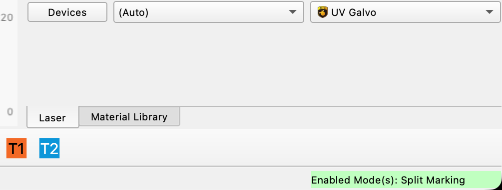
This switch controls whether Split Marking Mode is enabled. When enabled, you'll see a status indication in the bottom right corner of your screen:
Motor #
If your laser has two motor outputs, select which is connected to your Rotating or Linear table.
Axis Type
Select whether your device is a Rotating table that can make continuous, complete revolutions, or a Linear table that moves back and forth along an axis.
Axis Settings
Orientation
If your Axis Type is set to Linear, select whether it is orientated along your work area's X or Y Axis.
Reverse Direction
Enable Reverse Direction to tell your device to travel in the opposite direction it travels by default, without changing its orientation or rewiring it.
Steps Per
This value is the number of pulses required for the stepper motor to make one complete revolution.
Your table's manufacturer should provide you with the correct value for your device, or you can access its stepper driver and read or adjust the value there.
Unit Count
The amount of movement of the table that results from one complete rotation of the stepper motor.
- For Rotating tables the unit of movement is Rotations.
- For direct-driven tables, this value should be set to 1.
- For belt-driven tables, the value may vary based on gear ratio.
- For Linear tables the unit of movement is mm.
- This value should be set to match the amount of linear movement of your table that results from one complete revolution of its stepper motor.
Your table's manufacturer should be able to provide you with the correct value for your device — if you're unsure consult the documentation for your device, or contact the manufacturer.
Steps Per Unit
This value is automatically calculated by dividing your Steps per value by your Unit Count.
The calculated value equals the number of steps required to move your table in a single increment of your Unit:
- 1 complete rotation for Rotating tables
- 1 mm for Linear tables
Min Speed
The minimum speed at which in the table will travel, in Steps/second.
Max Speed
The maximum speed at which in the table will travel, in Steps/second.
Acceleration Time
Time to accelerate the table to full speed, in milliseconds. Lower values mean the table will accelerate faster.
Return to Start Position
Enable Return to starting point to have the table return to its starting point after the job is complete.
Return Speed
The speed at which the table will return to its starting position, in Steps/second.
Test
For Rotating tables, when the Test button is pressed, and both Steps per and Unit Count are correct, the table will rotate a full 360 degrees, pause, then rotate back to the starting point.
For Linear tables, when the Test button is pressed, and both Steps per and Unit Count are correct, the table will move 50 mm, then back to its starting point.
Homing
Home on Start
Enable Home on start to have LightBurn send a command to home a Linear table at the start of a job.
Note that homing may require special wiring — do not enable this setting if you are not sure if your table is wired for homing.
Speed
The speed at which the table will home.
Timeout
Amount of time before the table will abort the homing process.
Split Marking Window
When Split Marking is enabled, pressing the Start button in the Laser Window will bring up the Split Marking window.
Use the Split Marking window to jog your table into its starting position and establish the settings that determine how LightBurn will segment your graphics and move your table during marking.
Click any option in the image below to jump directly to the relevant section for that option, or scroll down for a list of options and descriptions.
Split Setup
Split Size
In Split Marking mode, graphics are divided into slices (segments). Each slice is marked on the object, the table advances, the next slice is marked, and so on, until the entire graphic has been marked.
The size of each segment is determined by the Split size setting. A larger Split size will reduce the time spent running the job, but it can be harder to dial in the settings such that there are no overlaps or gaps.
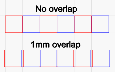
Overlap
To help eliminate visible gaps between slices, you can tell LightBurn to overlap them. Enter an Overlap value to produce that much overlap on the ends of each slice, like this:
Run Whole Shapes, If Possible
Enabling Run whole shapes if possible tells LightBurn to create splits in such a way that shapes are not broken into segments. The table will jog to the center of each valid shape and mark it in its entirety. This can produce a higher quality finish without gaps or misalignment within shapes.
Max Shape Size
When Run whole shapes if possible is enabled, Max Shape Size determines the maximum size of objects that the laser will run in their entirety. Objects larger than the Max Shape Size will be split into segments.
Output Center
Output will be centered on this line on the axis your table is set to. By default it is set to half of the maximum length of your Workspace, meaning output defaults to the center of the laser's field.
This setting allows you to shift the center position of your rotary output to compensate for the center of the rotary not lining up precisely with the center of the field. This value cannot be negative.
Show
The Show button commands your laser to Frame a line in the location Output Center is set to.
Run Shapes in Shape Order
Shapes will be run in their planned order, allowing the table to both advance and reverse.
Run All Shapes in Each Slice
All shapes in each slice will be run before the table advances, preventing the table from reversing.
Run shapes in shapes order vs. Run all shapes in each slice behavior comparison
Imagine your project has two layers, and you've selected Order by Layer in Optimization Settings.
If you select Run shapes in shape order, the laser will mark all splits containing the first layer, then reverse the table back to the beginning, and then run all splits containing the second layer.
If you select Run all shapes in each slice, the laser will run the first layer and then the second layer on each split, before advancing to the next split, until the job is complete.
Table Positioning
Position
The value displayed next to Pos. shows the current location of the table along the external axis.
Go to Zero
Commands the table to return to the zero point on the linear or rotating axis.
Jog
The Jog << / >> buttons command the table to advance forward or backward in the increment set in the field above the Go to Zero button.
Set Zero
Sets the current position of the table as the zero point.
Start, Pause, Stop
These options work exactly as they do in the Laser Window during standard marking operations to begin (Start), temporarily pause (Pause) a job until your press Resume, or permanently halt (Stop) a job.
Frame
Frames individual slices that show where graphics will be engraved on the surface of your object.
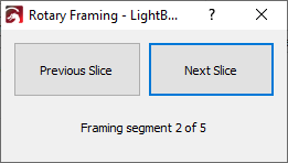
Click Previous Slice and Next Slice to command the table to jog forward or backward to frame each slice in order.
The current segment being framed and total number of segments are displayed beneath the buttons.
Framing slice size
The size of slices when framing is distinct from the user-specified Split size used during engraving.
Setup
Opens the Split Marking Setup window.
Sanity Check
Checks whether your settings make sense, including whether you have enabled Run whole shapes if possible but selected Fill all shapes at once in the Cut Settings Editor.