Dual Laser Control
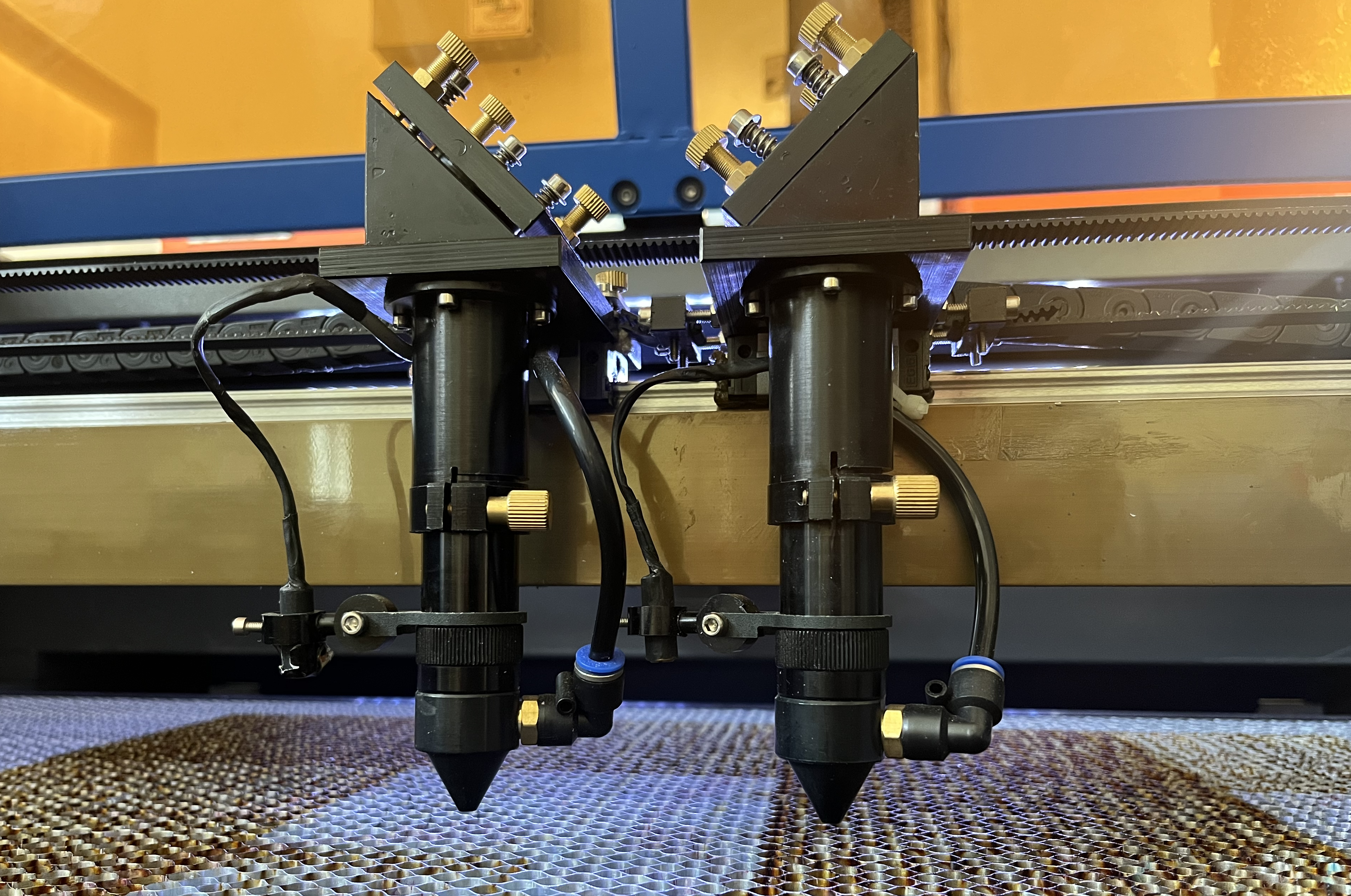
LightBurn provides special setup options for machines with two laser tubes. These settings are only available for users with DSP devices.
Laser 2 Controls
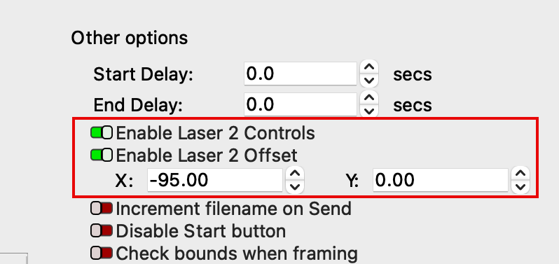
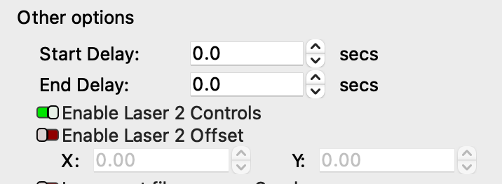
Two Laser 2 options are available in the Other options section of the Device Settings window (Edit ➝ Device Settings).
Turn on Enable Laser 2 Controls to expose switches in the Cuts/Layers window and Cut Settings Editor that will allow you to enable one or both laser tubes for a given layer, and adjust their power settings individually.
Turn on Enable Laser 2 Offset to specify an offset to account for the distance between the second and first laser head, if your laser has dual heads in addition to dual tubes.
Individual Laser Controls
The switches in the Cuts/Layers window and Cut Settings Editor are used to enable one or both lasers on a per-layer basis. Each laser's Max Power and Min Power settings can be managed individually, but all other settings are shared when both laser lasers are enabled at the same time.
In the Cut Settings Editor, both lasers' switches and power settings are visible simultaneously. In the Cuts/Layers window, select the button for the laser you wish to adjust, to show the switch and cut settings for that laser.
Both Lasers Enabled at Once
The option to enable both lasers at once is intended for lasers with dual heads. With both lasers enabled for the same layer, the lasers will run simultaneously in tandem, meaning two copies of the same output will be cut or engraved at once, without any offset applied to the output from the second laser.
Make sure your laser heads are physically spaced far enough apart from one another that each has room to cut or engrave the entire graphic, without overlapping or running into the side of your machine. This means that any graphic you run with both lasers enabled must be narrower than the distance between the two heads.
Only One Laser Enabled at a Time
If each of your laser tubes is optimized for different processes, you may choose to enable one laser for engraving and the other laser for cutting. Any layer or Sub-Layer can be set to output using only Laser 1 or only Laser 2.
To have one laser engrave a graphic and the other cut the outline of the same graphic, create a Sub-Layer for the layer the graphic is assigned to, and enable only the appropriate laser for the operation assigned to each Sub-Layer.
If you are engraving and cutting separate graphics in the same job, set each to their own layer, and enable only the appropriate laser for the operation assigned to each layer.
If each of your laser tubes also has its own head, in order for output from Laser 2 to align to output from Laser 1, you must measure and apply an accurate Laser 2 Offset.
See the following section for instructions on setting a Laser 2 Offset.
Laser 2 Offset
The X and Y fields beneath the Enable Laser 2 Offset switch in the Device Settings window are used to compensate for the distance between two laser heads. By shifting output to the 2nd laser head by specified X and Y values, output from Laser 2 will line up with output from Laser 1.
Follow the instructions below to measure the distance between Laser 1 and Laser 2 and apply appropriate offsets.
-
Before beginning this process, make sure Enable Laser 2 Controls is toggled on.
-
Load an inexpensive, expendable material into your laser's bed. Make sure it is large enough for both laser heads to mark it at once. Position it beneath both laser heads.
-
Use the Draw Lines tool to create a short, perfectly vertical line in your LightBurn workspace.
Tip
Use Grid Snapping or the Edit Nodes tool's Align to Angles option to ensure the line is perfectly vertical.
-
Assign the vertical line to a layer set to Line mode.
-
In the Cut Settings Editor, enable both Laser 1 and Laser 2, and apply appropriate settings to mark the vertical lines on the material without cutting through.
-
Select Current Position as your Start From mode.
- Press Start to mark the lines on the material.
-
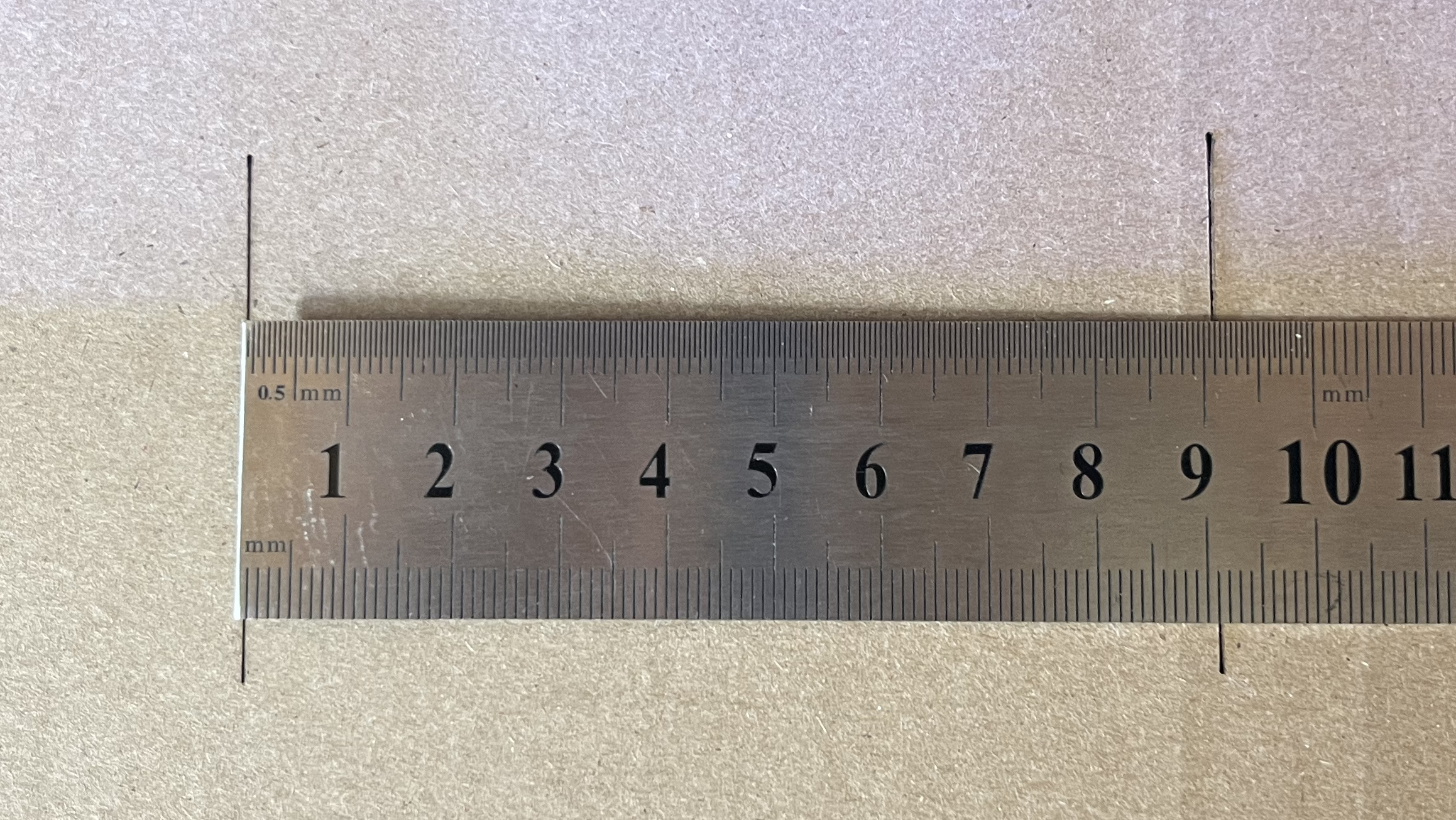
Measure and record the distance between the lines.
-
In the Device Settings window, turn on Enable Laser 2 Offset.
-
If Laser 2 is farther from your machine's origin than Laser 1, enter the measured distance between the lines as a negative value in the X field. If it closer to the origin, enter the distance as a positive value.
Note
The machine's origin is the location it homes to when it first starts.
-
Rotate the vertical line 90 degrees to make it horizontal.
Tip
press the . key to rotate objects 90 degrees clockwise.
-
In the Cut Settings Editor, add a Sub-Layer to the layer the horizontal line is assigned to.
- You'll now have two Sub-Layers. Keep both set to Line mode.
- Disable Laser 2 for the first Sub-Layer, but enable it for the second Sub-Layer. Disable Laser 1 for the second Sub-Layer.
- On the second Sub-Layer, apply appropriate settings for Laser 2 to mark your material.
- Select Current Position as your Start From mode, and make sure the first laser head is positioned over the material.
- Press Start.
- If you measured the distance between the vertical lines accurately in Step 8, each horizontal line should line up perfectly in the X dimension.
- If they are misaligned and the output from Laser 2 shifted in the opposite direction of what you expected, reverse the sign of the X dimension Laser 2 Offset in the Device Settings window. In other words, if the value is positive, make it negative, or vice versa.
- If they are misaligned but Laser 2 output was shifted in the correct direction, repeat Steps 1-8, taking care to measure as precisely as possible.
-
If the horizontal lines are aligned in both the X dimension and the Y dimension, the process is complete. If they are aligned in X but misaligned in Y, measure the distance between the 2 lines.
-
If the line output by Laser 2 is farther from your machine's origin than the one output by Laser 1, enter the measured distance between the lines as a negative value in the X field. If it closer to the origin, enter the distance as a positive value.
Note
The machine's origin is the location it homes to when it first starts.
-
Mark the horizontal lines again to verify alignment.
- Reverse the sign of the Y offset if output was shifted in the incorrect direction.
- If output was shifted in the correct direction in Y but is still misaligned, reset the Y offset to 0 and repeat Steps 17-20.
