Steps / mm
If what you are seeing come out of your laser looks like it's squished or stretched in one or more axis, it's very likely because your steps/mm are configured incorrectly.
All laser cutters / engravers require that they be configured with the correct steps/mm (steps per millimeter) setting to function correctly. If your movement is already close, LightBurn has a built-in Calibrate Axis tool that will allow you to easily dial in the correct setting. If you would like to better understand how the steps/mm setting works and how to actually find or calculate the true value, read on.
Background
Your laser moves by using stepper motors which, unlike basic motors, don't spin continuously but can be moved in discrete steps, each of which is a specific number of degrees in a full rotation. For example, the most common motor type has a 1.8° step angle, meaning that a full rotation is 200 steps (360° / 1.8° = 200).
So in order to tell your machine how to move the correct distance it has to know how many steps to instruct each motor to move. What that value is, however, depends on not just the motor but the rest of the machine's setup. For small, diode-base lasers a common setup might look like:
- 1.8° Nema 17 stepper motor
- GT2 belts (2 mm distance between each tooth)
- 20 tooth GT2 pulley
Fortunately, calculating this is made easy by many great online tools, like this Stepper Motor Calculator.
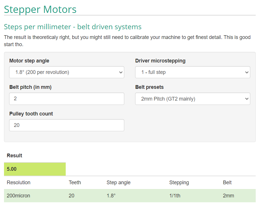
So for this configuration, as is, you would setup the calculator as shown:
You would needs 5 steps per mm of movement. This is because a 20 tooth pulley represents 40 mm of movement for one full rotation (20 teeth * 2 mm per tooth) and there are 200 steps per full rotation. So 200 / 40 = 5.
Microstepping
However, almost no machines will ever run in "full step" mode as shown in the example above. As you can see at the bottom of the example above the resolution is 200 micron or 0.2 mm. That means the absolute smallest distance that can be moved is 0.2 mm, which is not nearly good enough. Modern stepper motor drivers, however, can pull off a trick known as microstepping in which they can move in steps between the natural steps of the motor. A common option is 1/16th microstepping which means that it divides each natural step into 16 sub-steps, multiplying the number of steps required per full rotation from 200 to 3200!
As you can see now the steps/mm value jumped from 5 to 80 and now has a resolution of 12.5 micron or 0.0125 mm.
What settings does your machine use?
The above is merely explaining the theory, now we need to put it all together.
First off, the best place to find your correct steps/mm setting is generally going to be from the manufacturer of the machine (unless you built it yourself). We highly recommend starting by looking for the correct settings direct from the source.
Barring that information being available, it can be discovered with a little work.
Motors
It is highly unlikely the motors you are using are anything other than the 1.8° variety. Sometimes 0.9° are used and those are very often marked as such on the motor body somewhere. You will also likely find a model number marked somewhere on the motor. Find that and look it up online, for example: 17HS19-2004S1
You will then typically be able to find specs or a datasheet on that specific motor model which will tell you the step angle.
Belts
Small hobby diode lasers typically use GT2 (Sometimes called 2GT) belts which is just the name of a common belt profile that has a 2 mm pitch. The pitch of a belt is the distance from the center of one tooth to the center of the next. You can use calipers or an accurate ruler to check if you are unsure. Just note that belts will always use nice round numbers. Commonly you will find 2 mm, 3 mm, or 5 mm pitch. Anything beyond that is unlikely to be used in a laser.
Once you've found this value enter it in the Belt pitch field in the stepper motor calculator, or use one of the Belt presets from the drop-down.
Screws
Some machines use lead screws instead of belts, such as the 3018 CNC machines which we see converted to laser use very often. Determining the pitch of a screw is very much the same, except that you need to follow a single thread of the screw (sometimes they have multiple threads unlike a bolt might) for one full rotation (it may be helpful to mark it with a Sharpie) and then measure the distance from start to finish of that rotation.
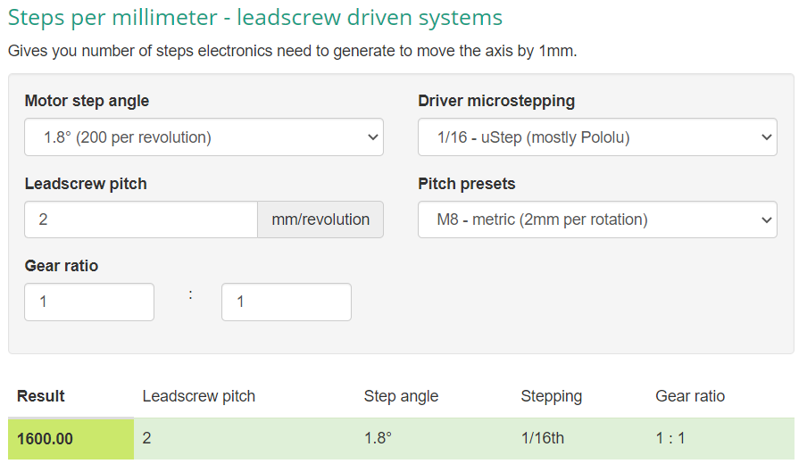
Just like with the belts there should be no odd numbers here as there are very standardized screw pitches. 2 mm, 4 mm, and 5 mm are very common for this application. Just be sure to use the leadscrew driven systems version of the calculator, lower on the page:
Motor Driver Microstepping
Finally you need to determing what microstepping value is configured for your drivers. This is either something that cannot be changed on your particular controller (in which case you need to find out from the manufacturer) or can be changed via DIP switches or jumpers.
Many GCode based devices use what are commonly referred to as "StepStick" style motor drivers - a little 0.6" x 0.8" circuit board with 8 pins on each side that plugs into your controller. On the controller will often be either jumpers or DIP switches to configure 3 different states that controll the microstepping.
These will typically be labeled MS1, MS2, MS3 or CFG1, CFG2, CFG3. You will need to then determine what driver chip is being used by looking at the black IC on the StepStick board. You may need magnification to read the markings. Once you know the type you can lookup the configuration options online for that specific driver.
For example the common (though a bit old at this point) DRV8825 from Texas Instruments has the following configuration table:
| CFG1 | CFG2 | CFG3 | MicroSteps |
|---|---|---|---|
| O | O | O | 1/1 |
| X | O | O | ½ |
| O | X | O | ¼ |
| X | X | O | ⅛ |
| O | O | X | 1/16 |
| X | X | X | 1/32 |
O means that config pin is left open (no jumper) or off (in the case of a DIP switch). X means closed (with jumper) or on. So, for example, with no jumpers on CFG1 and CFG2 but a jumper on CFG3, the driver would be running in 1/16th microstepping mode. As in it divides each step into 16 sub-steps, therefore multiplying the total number of steps per revolution by 16.


