Rotary for Galvo
Rotaries are used to turn cylindrical objects so that their surfaces can be marked by a laser. In order to use your laser with a rotary, you must first establish several important parameters in the Rotary Setup window that control the rotary's motion and adjust the output sent to your laser.
To open Rotary Setup, go to Laser Tools → Rotary Setup (Ctrl/Cmd+Shift+R), or click the rotary icon in the Modes toolbar.
Rotary Setup
Rotary Type
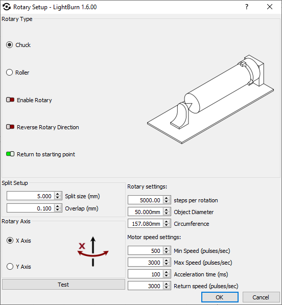
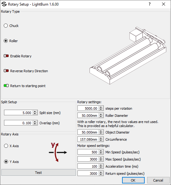
Select whether your rotary is a Chuck or Roller style rotary. Chuck rotaries have adjustable jaws that grab and hold objects, while Roller rotaries have revolving rollers or wheels that objects are placed on top of.
Enable Rotary
This switch controls whether Rotary Mode is enabled. When enabled, rotational commands are sent to the laser to control rotary motion, and output is split into segments.
If Show rotary enable in main window is enabled in your LightBurn settings, you can also enable or disable Rotary Mode using the switch in the Laser window.
Rotary Settings
Steps Per Rotation
Set the steps per rotation value to the number of motor steps required to spin the rotary one complete rotation.
When the Test button is pressed, it should rotate a full 360 degrees, pause, then rotate back to the starting point.
If this value is incorrect, output will be warped or disconnected.
In most cases, steps per rotation will be provided by the manufacturer of your machine, either as a screenshot of the rotary params page in EZCAD or in a text document.
Common steps per rotation values for Galvo rotaries are 9,600, 12,800, and 25,600.
Warning
With a Roller style rotary, it is the roller or wheel driven by the motor that must make one complete rotation when you click the Test button, and not an object on the rotary.
Roller Diameter
This option is only presented for Roller style rotaries. Carefully measure the diameter of the roller or wheel driven by the rotary motor.
Once this measurement is accurately identified and set, it never needs to be adjusted again. If it is innaccurate, output will be warped or disconnected.
Object Diameter
For Chuck style rotaries, carefully measure and enter the Object Diameter of the item on your rotary. This value must be updated every time you place an object with a different diameter on your rotary. If it is innaccurate, output will be warped or disconnected.
For Roller style rotaries, Object Diameter does not affect output, but can be entered here to calculate the Circumference of your object, which can be useful for adjusting the size and relative position of your graphics.
Tip
Use high precision calipers to guarantee the accuracy of your diameter measurement.
If your object is tapered, check out our Taper Warp tool.
Circumference
Object Circumference is automatically calculated based on the value entered in the Object Diameter field.
Use this value to adjust the size of your graphics — for full wrap designs, the combined height of your graphics should be identical to the Circumference, if the rotary is set to the Y Axis, or the width, if it is set to the X axis. See below for information on Axis selection.
Split Setup
Split Size
When working with a rotary and Galvo laser, graphics are split into segments (slices). Each slice is marked on the object, then the rotary turns, the next slice is marked, and so on, until the entire graphic has been marked.
The size of each segment is determined by the Split size setting. If your object is tapered, irregularly shaped, or not perfectly aligned with the rotary axis, using a small Split size can help reduce gaps or misalignment of the splits.
A larger Split size will reduce the time spent running the job, but it can be harder to dial in the settings such that there are no overlaps or gaps.
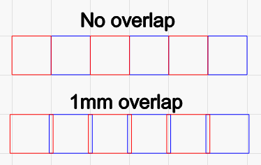
Overlap
To help eliminate visible gaps between slices, you can tell LightBurn to overlap them. Enter an Overlap value to produce that much overlap on the ends of each slice, like this:
Tip
If you are removing paint, anodizing, or other surface coating, using a small overlap is recommended. If you are annealing or marking the material directly, adding overlaps may produce visible artifacts.
Rotary Axis
Select the X Axis if your rotary is oriented across your workspace from top to bottom (or vice versa), and will be rotating in the direction of X Axis motion.
Select the Y Axis if your rotary is oriented across your workspace from right to left (or vice versa), and will be rotating in the direction of Y Axis motion.
Tip
When rotating on the X Axis, you'll want to engrave along the Y Axis, with a Scan Angle of 90 or 270. When rotating on the Y axis, you'll want to engrave along the X Axis, with a scan angle of 0 or 180.
Motor Speed Settings
Min Speed
The minimum speed at which in the rotary will rotate, in pulses/second.
Max Speed
The maximum speed at which in the rotary will rotate, in pulses/second.
Acceleration Time
Time to accelerate the rotary to full speed, in milliseconds.
Tip
If your rotary is losing steps, or an object on a Roller type rotary is slipping, reduce Max Speed and increase Acceleration time.
Return Speed
The speed at which the rotary will return to its starting position, in pulses/second.
Reverse Rotary Direction
Enable the Reverse Rotary Direction switch if the output is backwards or sliced in the wrong order.
Return to Starting Point
Enable Return to starting point to have the rotary return to its starting point after the job is complete.
Rotary Marking Window
When Rotary Mode is enabled, pressing the Start button in the Laser window will bring up the Rotary Marking window, shown here:
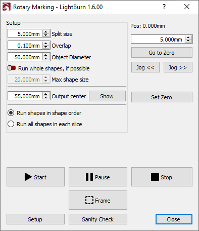
Split Size and Overlap
Split size and Overlap in the Rotary Marking window are linked to the values set in Rotary Setup window. Changing either value in either window automatically changes it in both places.
See above for more information on these settings.
Warning
You will see a warning message if you set Split size lower than the smallest possible Split size, as determined by your object's diameter and rotary's stepper resolution.
Object Diameter
Object Diameter is linked to the value set in the Rotary Setup window. Changing the value in either window will automatically update it in both places.
See above for more information.
Note
This option is not presented in the Rotary Marking window when working with a Roller style rotary.
Run Whole Shapes, If Possible
Enabling Run whole shapes if possible tells LightBurn to create splits in such a way that shapes are not broken into segments. The rotary will jog to the center of each valid shape and mark it in its entirety. This can produce a higher quality finish without gaps or misalignment within shapes.
Max Shape Size
When Run whole shapes if possible is enabled, Max Shape Size determines the maximum size of objects that the laser will run in their entirety. Objects larger than the Max Shape Size will be split into segments.
Warning
If Max Shape Size is set too high, the laser's beam may go out of focus toward the edges of large shapes due to the curvature of the object on your rotary, and mark weakly, or not at all.
Output Center
Output will be centered on this line on the axis your rotary is set to. By default it is set to half of the maximum length of your workspace, meaning output defaults to the center of the laser's field.
This setting allows you to shift the center position of your rotary output to compensate for the center of the rotary not lining up precisely with the center of the field. This value cannot be negative.
Show
The Show button commands your laser to Frame a line in the location Output Center is set to.
Run Shapes in Shape Order
Shapes will be run in their planned order, allowing the rotary to rewind. This option is best suited to Chuck style rotaries.
Run All Shapes in Each Slice
All shapes in each slice will be run before the rotary advances, preventing the rotary from rewinding. This option is best for Roller style rotaries, where objects may lose position due to rewinding.
Positioning
Position
The value displayed next to Pos. shows the current location of the rotary along the axis of rotation.
Go to Zero
Commands the rotary to return to the zero point on the axis of rotation.
Jog
The Jog << / >> buttons command the rotary to turn forward or backward in the increment set in the field above the Go to Zero button.
Set Zero
Sets the current position of the rotary as the zero point.
Start, Pause, Stop
These options work exactly as they do in the Laser window during flat marking operations to begin (Start), temporarily pause a job until your press Start again (Pause), or permanently halt (Stop) a job.
Frame
Frames individual slices that show where graphics will be engraved on the surface of your object.
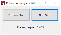
Click Previous Slice and Next Slice to command the rotary to turn forward or backward to frame each slice in order.
The current segment being framed and total number of segments are displayed beneath the buttons.
Framing slice size
The size of slices when framing is distinct from the user-specified Split size used during engraving. Instead, the amount of slices is automatically determined based on the size of your object and the graphics you'll be engraving.
Larger objects have less curvature and therefore more area that the red dot can reach and adequately frame, often resulting in fewer framing slices for larger objects than smaller ones.
Setup
Opens the Rotary Setup window.
Sanity Check
Checks whether your settings make sense, including whether your Scan Angle is set to engrave along the dimension of rotation, or have enabled Run whole shapes if possible but selected Fill all shapes at once in the Cut Settings Editor.
Positioning Graphics
When using a rotary with a Galvo device, the center line of your LightBurn workspace represents the zero position of the rotary. If the rotary is set to the Y Axis, it is represented by the horizontal center line, and if it set to the X Axis it is represented by the vertical center line.
Tip
Enable Show work area center cross for a clear visualization of your workspace's center lines.
The farther away from the center line a graphic is positioned in LightBurn, the more the rotary will turn to reach the location it is to be marked on your object.
If graphics are straddling the center line, the rotary will first turn in one direction to reach the furthest extent of the graphics, then begin marking, eventually crossing the zero point to mark graphics positoned on the other side of the center line.
To have the rotary begin marking without turning first, position your graphics so that their edge is just above or below (if the rotary is set to Y) or to the left or right (if the rotary is set to X) of the center line of your workspace.
Tip
Use the X and Y Position fields in Numeric Edits toolbar to guarantee precise positioning.
Graphics can be positioned as normal in the dimension the rotary is not set to rotate on, to adjust the location they will output to along the object you're marking.
Focusing
See Focusing for more information.
Troubleshooting
- If output is stretched or there are gaps between slices, double check the steps per rotation and Object Diameter values. If you are using a Roller style rotary, check Roller Diameter instead of Object Diameter.
- In the Rotary Setup window, make sure the rotary — and not an object on the rotary — makes a single 360 degree rotation before returning to the starting location when you click the Test button.
- Use high precision calipers for best results when measuring the diameter of your object or roller.
- If output to your rotary is sent to the far left or bottom of your workspace, check to make sure the Output Center value is not set to 0.
- If your graphics are only outputting as a line or narrow band on your object, switch to the alternate Rotary Axis setting, or change the physical orientation of your rotary to match the current setting.
- If output to your rotary is mirrored or reversed, enable Reverse Rotary Direction.