Cylinder Correction Marking
Cylinder Correction (called ProjectMark in EZCAD) warps the output of your design to correct for the expansion that happens when you mark on a cylindrical object, like a cup or tumbler, without using a rotary.
Note
This feature is currently only avalible on galvo machines. While it is on the roadmap to enable this functionality for DSP and GRBL, this will not present itself on DSP or GCode machines until that change is made.
Theory
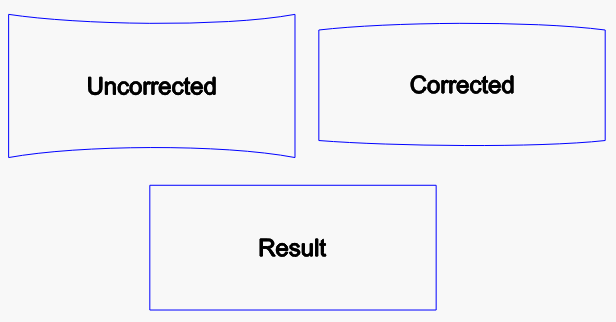
In the image below, the blue shapes represent a rectangle. If you were to project a rectangle directly onto a cylinder, the sides of the rectangle would hit the cylinder at a lower point than the middle. Since the laser is projected from a single point above your object, the extra distance means the sides of the rectangle will widen and curve, like the rectangle below labeled "Uncorrected".
With Cylinder Correction mode enabled, LightBurn will alter the data sent to the laser to compensate for this. LightBurn sends something similar to the "Corrected" image, and when engraving your object, the effects negate each other. This produces crisp, significantly less distorted results, like the "Result" shape shown below.
Lens Selection
Using this feature is dependent on being able to make a mark on your target object across a potentially wide focal range. For example, if you have a 75 mm diameter tumbler and are engraving a 50 mm wide graphic, there will be a roughly 10 mm difference in focal distance from the center to the edge of that graphic.
Due to this, you will want to select a lens that has a wider "field" (working area) for your galvo laser. For example, a 110 mm field lens (f=160 mm) may only have a workable focal range of around 1.5-2 mm. However, a 300 mm field lens (f=430 mm) should be able to handle a 10 mm range relatively easily.
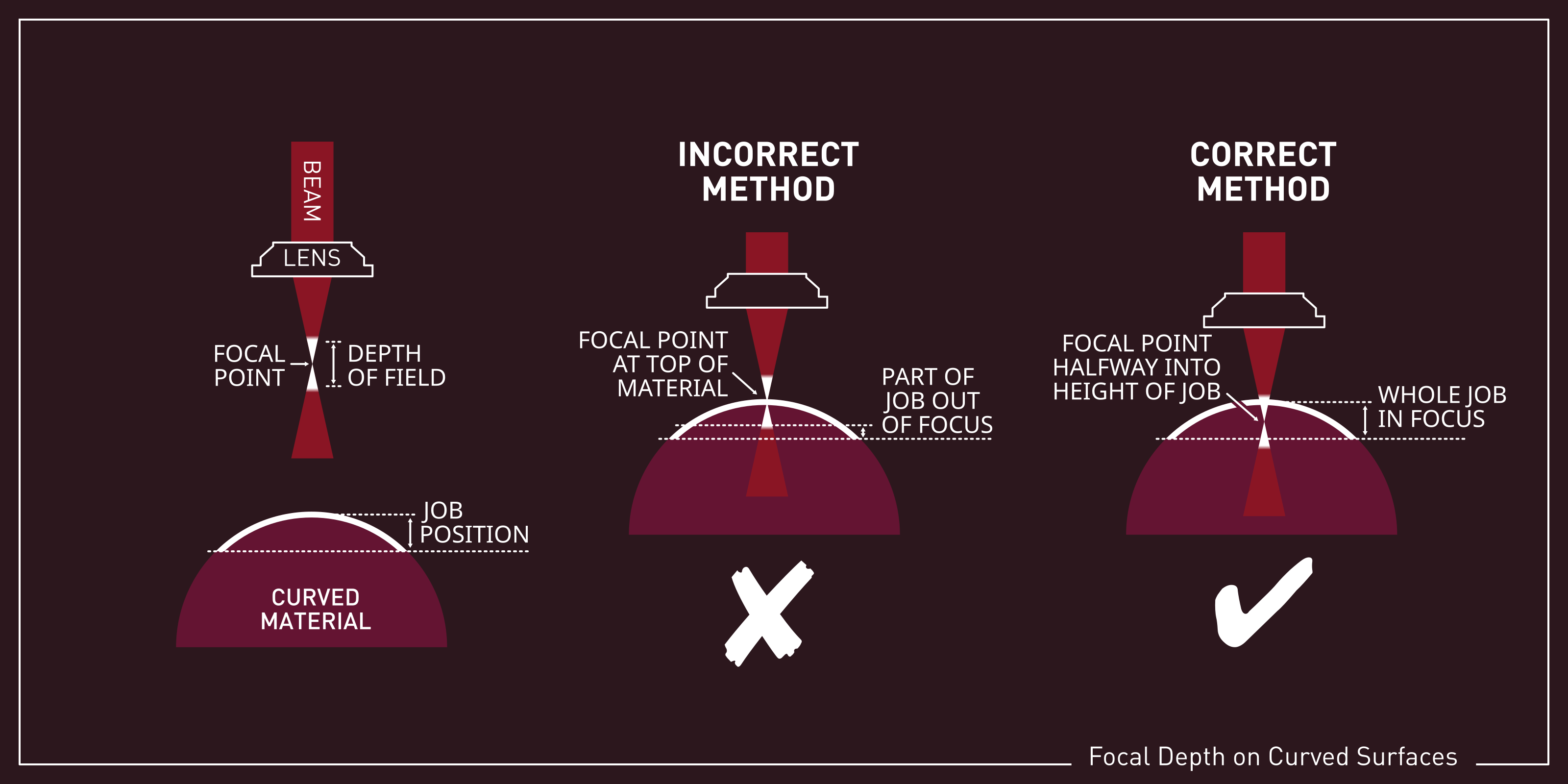
You will also want to focus your lense partway into the surface of your cylinder, to take advantage of the full depth of field of your lens, as described in the image below.
Design Placement
LightBurn will always assume that the center of the provided shapes are at the center of the object you are engraving on. This includes if you are using Cut Selected Shapes - where it will base the center calculation on only those shapes. It is done this way so that you do not have to always place your object exactly at the center of your machine working area. If, for example, your placement jig has to be 20 mm off center due to the threaded grid holes being off center, you can simply adjust your design to be 20 mm off center to match. You can, of course, verify the correct placement using the framing option in the Laser panel.
This assumption is made because if the object is off center from the actual galvo center, the laser can physically reach more of one side of that curved surface than the other. LightBurn will actually warp each side of your design more or less according to this offset.
It also affects the valid boundary in which your design can be placed for a given mirror distance and object diameter.
Setup
To enable it, go to Tools > Cylinder Correction Setup, and you'll be shown this screen:

Start by toggling the "Enable Cylinder Correction" option at the top. Note: this is not preserved across LightBurn sessions like it is for some rotaries. You will have to re-enable it any time you restart LightBurn and would like to use this feature.
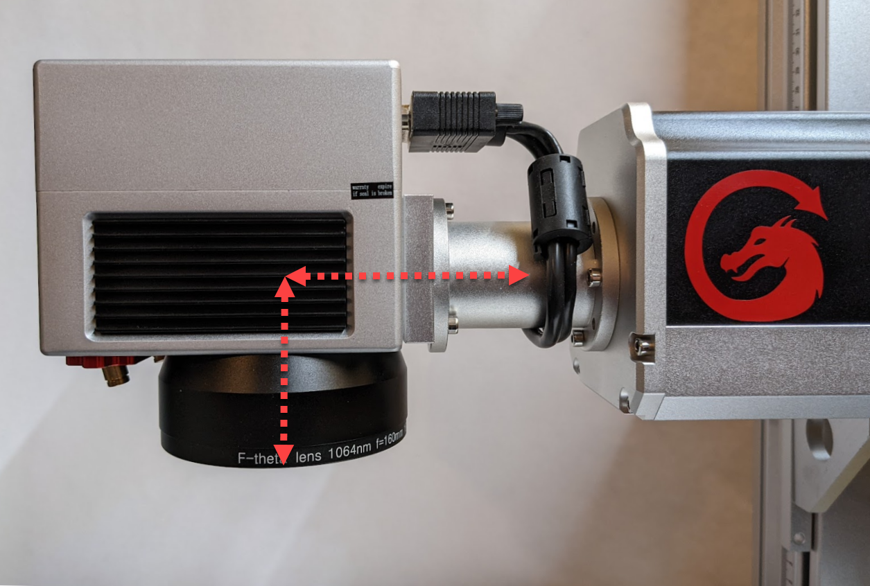
Next, set your mirror distance from the surface of your object. Note: this is not the focus distance from the lens, but actually to the mirrors. It is relatively easy to find this distance however. There is typically a tube connecting the galvo head to the laser source and the mirrors are generally centered along that tube.
In the image below, you can see the center plane of that tube marked along with the distance from the bottom of the lens to that center plane marked. Assuming you measure your focus distance from the bottom of the lens to the surface of the object, simply measure the distance from the bottom of the lens to the center plane of the tube and add that to your focus distance. Use that value for the mirror distance.
Finally enter your object diameter and choose the axis along which your target object curves.
Valid Boundary
Given that the laser is being projected from a fixed point onto a curved surface, there are limits to where on your engraved object your laser can actually reach.
In the Cylinder Correction Setup dialog, shown above, there is a Show Valid Boundary button at the bottom. Click on this and it will insert a rectangle, on the T0 tool layer, into your design, showing you the area in which your design can be placed.
This valid boundary area is also affected by how far from center your object is.
If you attempt to run an cylinder corrected engrave or even show the preview while your design is outside of this boundary, you will be presented with the following dialog:
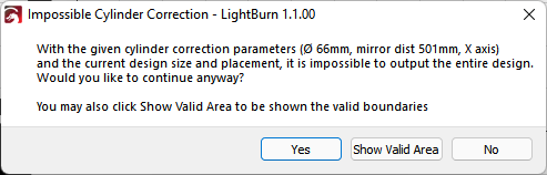
If you choose to continue anyways, the areas outside of the valid boundary will be automatically cut off from the output. In the image below you can see it has actually removed the portions outside of the valid boundary area, shown in orange at the left.
You can also, from that dialog choose to have it show you the boundary just as you would in the setup dialog.