Configuring Galvo Settings
Note
If you did the EZCAD/SeaCAD parameter import as part of setting up the device, you can likely skip this part, though we do recommend verifying that everything came across correctly. If you didn't import those settings, continue reading.
LightBurn needs to know more about your galvo laser before you can use it effectively. Below is an explanation of every currently listed item in the Device Settings  for Galvo devices.
If you're entering settings manually based on existing EZCAD/SeaCAD installation, you can run the software and take screenshots of the existing settings in the Param ( F3 ) pages.
Run LightBurn, select your Galvo laser, then click Edit → Device Settings, or click Device Settings on the toolbar.
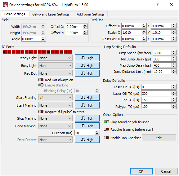
Basic Settings
Field
These fields describe the area that the lens installed in the galvo can physically cover when focused. Changing the lenses always requires going through the setup and calibration to adequately tune and dial in galvos.
Size
The maximum area the lens installed in the laser can cover. This value is also used to set up the work area in LightBurn.
Angle
Rotational correction for the field - if you're correcting for a rotated galvo head relative to the physical fixturing pattern, you can rotate it to behave as if it were square with this value.
Offset (v1.4+)
You can fine tune the position of the field using x and y offset
Red Dot
The red dot laser is a separate mechanism that is in line with the optics of your galvo laser souce. It may require fine adjustment to get it aligned with those optics, and this is where those settings come from. While generally provided as part of the EZCAD/SeaCAD config file imported during Setup, they may also be found in your installation media as a screenshot or other text file.
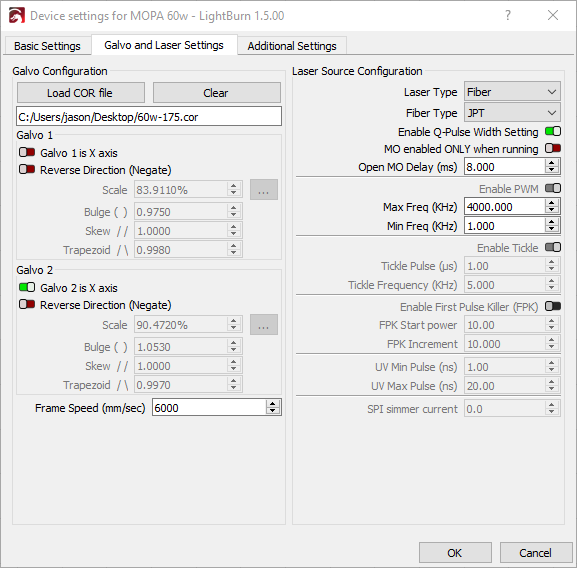
Galvo configuration
Load COR File
A COR file is an EZCAD or SeaCAD lens correction file. LightBurn has the ability to import COR files and automatically apply the lens correction values they contain. If you use the EzCAD/SeaCAD configuration file import during Setup and a COR file is present, it will be loaded automatically. If you skip the import process or create a new COR file, you can load it here.
Otherwise, this field can be left blank, and the scale, bulge, skew, and trapezoid settings can be imported directly from the markcfg7 file, or entered manually in Per Galvo Settings.
Per Galvo Settings (Galvo 1/Galvo 2)
Each galvo head is responsible for an axis, and has fine-tuning that can be performed to get it operating optimally.
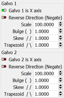
Galvo (N) is X Axis
This toggle is linked for both galvo mirrors, allowing you to specify which mirror is used for the X-motion of LightBurn.
Reverse Direction (Negate)
This flips the output behavior of an axis in the event the control signal is linked backwards to the motion of the mirror.
Scale, Bulge, Skew, and Trapezoid
A more in-depth explanation of the below settings can be found in the Lens Correction section.
Scale
Perentage to scale the output axis by.
Bulge
Distortion near or at the center of the engraving field.
Skew
Distortion at the edges (corners) of the fields, pulling them towards a cardinal direction.
Trapezoid
Corner tapering adjustment, to fix keystoning.
Other Options
Play sound on job finished
This feature mirrors that of EZCAD, causing the computer to play a sound when your current run is done, in leiu of all galvos having a window.
Require framing before start
This option forces the user to use framing mode and align their workpiece before engraving directly. It makes the Start Button in the Laser Window open the Framing Dialog instead.
Enable Job Checklist
When this option is enabled, LightBurn will display a textbox with a list of items before running the laser. The user will need to press "OK" to confirm they're ready before the laser will start.
The Edit button allows you to create or edit this list.
Laser Source Configuration
Danger
All of these settings should be imported from EZCAD, manually changing them to "guess and check" settings is not the correct course of action. Doing so may damage your laser, proceed with caution!
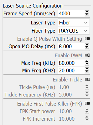
Frame Speed
This is the maximum speed of the red dot framing tool in your galvo.
Max Speed (LightBurn 1.7+)
Use this setting to limit the maximum speed a cut can be set to.
Laser Type
This refers to the specific type of galvo laser in use. Fiber or CO2 are the current options.
Fiber Type
The specific manufacturer, or granular type of laser. This may reveal other settings depending on what type and category of laser is in use.
Enable Q-Pulse Width Setting (MOPA)
This is a MOPA specific laser setting to adjust the fine length timing of the pulses from the laser. The larger the timing, the less dense the pulse impact is.
Open MO Delay (ms)
MOPA permits a wider frequency range comparatively to Q switch laser types, and this delay allows you to adjust this fine control.
Enable PWM
This permits adjustment of the valid range of PWM timings on CO2 galvo lasers.
Tickle
CO2 lasers require constant low power to be able to fire at lower power densities consistently and reliably. Use of a tickle permits adjusting the controlled location of that threshold to produce better lower power engravings.
These will be provided by your manufacturer.
First Pulse Killer (FPK)
This setting is also CO2 specific. To enable the initial power-on of a CO2 tube, there's a higher power draw needed to energize it. FPK lets you choose and tune that first pulse to get to the normal operation energy.
This setting can be found via trial and error if needed.
IO Ports
These are external switches or features attached to the controller on the board.
The High / Low toggle indicates whether the device is normally high, or normally low electrically, and determines what signal to interpret as being toggled.
Not all of these may exist, or be enabled on all galvos. If not, the port number will be shown as "None".
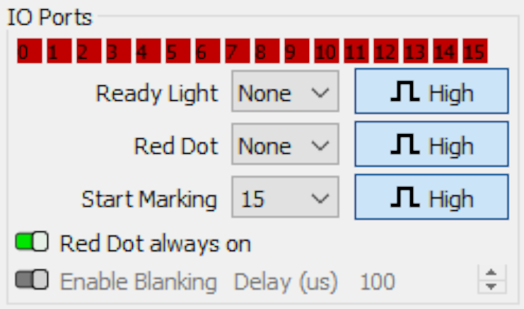
Red 0 through 15
These red/green rectangles represent the pin state of the Ezcad board inside your galvo laser at any given time, and the port number on the controller. This is useful for diagnosing floating electrical connections, loose wires, and a potential default setting dependent on a foot pedal.
Info
Within LightBurn, a red indicator means the port is "LOW", or off, and green means the port is "HIGH", or on. Some manufactured boards are active LOW as opposed to active "HIGH". If all ports are green by default, you'll likely need to change your trigger type to "LOW" from HIGH.
Ready Light
This is the selector to toggle LEDs on the galvo head, aimed at the workpiece.
Red Dot
This is the selector for the external Red Dot enable.
Start Marking
This is the selector for starting an engraving job as set up, typically triggered with a foot switch of some kind on the laser. Like mentioned in IO Ports, a user can change the pin assignment to match that of the board's foot pedal or start signal, the signal trigger type, or disable it entirely. The former is useful to use a foot pedal; the latter for safety.
Danger
Prevent accidental laser activation when using galvo lasers without a foot pedal switch by explicitly setting the "Start Marking" pin to "Disabled". Some galvo controllers do not adequately electrically protect the circuit from stray voltage and static that may generate readable signals that will be sent to LightBurn.
LightBurn has debouncing in software to mitigate this as much as possible in 1.2.02. Please update to 1.2.02 or later to ensure you have this functionality automatically in place.
Red Dot always on
This setting forces the external red dot alignment spot to always be on, permitting constant use or disabling it if desired.
Enable blanking
This option allows you to attempt to turn off the red dot internal to your galvo between drawing shapes and is not supported on all devices.
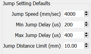
Jump Setting Defaults
These settings control the speeds by which to toggle, offset, delay, or fudge the source enable and galvo head motion.
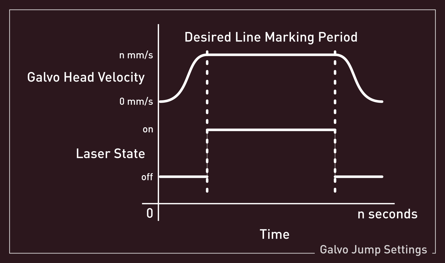
Delay Defaults
Laser on TC (μs)
When attempting to mark, the physical mirrors of the galvo head must reach the desired speed before they begin marking. This fine-tuning allows the user to reduce the burn-in potential during that initial acceleration by adjusting the source timing.
Laser Off TC (μs)
Similarly to the above, when the mirrors of the galvo head must slow down as they attempt to end a marking move, there may be a burn-in effect while slowing down. This setting allows the end timing to be adjusted finely.
End TC (μs)
This setting adjusts how long the laser waits at the end of a series of vectors. Due to the fact the laser will physically lag behind the commanded state as decided by any software, this delay permits adjustment similarly to the Laser Off TC.
This setting applies to any marking move where the laser is turned off after execution.
Polygon TC (μs)
This setting adjusts how long the laser "waits" at the end of each segment of a polygon, permitting the laser to settle appropriately, compensating for the same lag as outlined in End TC. This adjustment will only apply to polygonal execution.
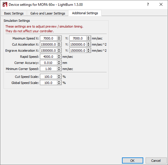
Additional Settings
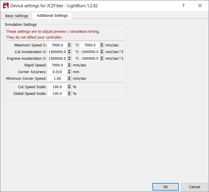
This settings tab consists of specific timing adjustments for simulation and preview, entirely for the Preview Window. The galvo can function even if these are set incorrectly, so long as the other timings and adjustments are correct.
If the estimate is significantly off from the timings in practice, we recommend editing these settings to match the main device settings .