Changing A Lens
To ensure best performance following a lens swap in LightBurn when using a galvo, there are several changes and settings you'll need to confirm first. Some manufacturers give you the calibration information for your new lens, and it's highly suggested you check their website before proceeding to find this manually.
Physical Lens Swap
This video guide from Laser Everything covers the physical installation of the lens, as well as many of the items outlined below with EZCAD analogues. It's suggested this video by Laser Everything is reviewed to help ensure the lens swap doesn't damage your machine or hurt you in the process.
Duplicate Original Laser
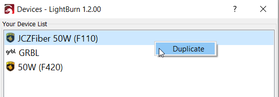
In many cases, changing the galvo lens means that you'll need to adjust many settings and recalibrate it, making it a "new" machine when doing so. To duplicate a laser device in LightBurn, click "Devices" in the "Laser" window, and right click on the given laser to duplicate it.
Be sure to give the duplicate a descriptive and accurate name to contrast it to the original, and ensure that's the one you'll be editing.
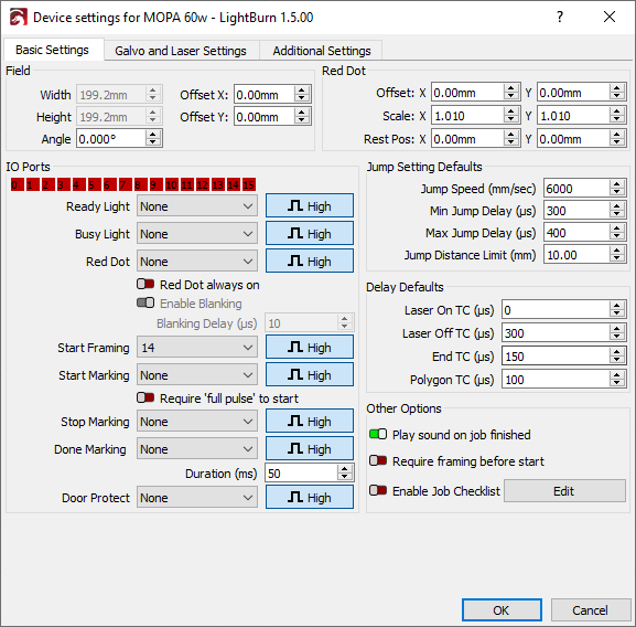
Field Size
When changing lenses, the effective Field Size of your laser will also change. The Field Size for your lens is usually listed on the manufacturer's website.
Focus
After changing lenses physically, you'll need to adjust the focus of the laser even without other calibration being done yet to ensure the results are as good as possible.
Spend time and reference the steps outlined in Focusing to ensure your galvo's output is crisp and in focus; keep in mind your red dot framing may no longer be in focus due to the focal length changes.
Scale, Bulge, Skew, Calibration
Once your galvo is focused, you'll need to adjust the bulge, skew, trapezoidal calibration as best you can to match this new lens. Please see Lens Correction and the specific Device Settings for Galvo to get more in-depth explanations of the calibration settings.
Warning
While your initial testing may have been done in the center of your engraving field, it's suggested that you perform one or more tests at the edge of your field to fine-tune the Scale/Trapezoid/Bulge/Stretch to ensure accuracy and consistency.
In the event you find the design severely distorted at the edges but not at the center, it's likely your Field Size was set incorrectly. You'll need to follow the steps from the beginning to try and mitigate this.
Scale
In order to test scale, it's suggested you attempt to frame a square of known size in LightBurn (say, 60 mm), and measure the corner-to-corner with calipers to adjust your X and Y scale as needed.
Bulge
Following that, you'll want to measure your design bulge; frame a square nearly as large as your field allows (errors are amplified at the edges of a galvo). Put the edge of a flat surface directly between the two corners of a side and check to see if the line bulges into or past the straight edge, and adjust your bulge settings accordignly. Repeat this step for both axes.
Trapezoidal
Frame a square nearly as large as your field allows (errors are amplified at the edges of a galvo). Measure the length of the top edge and compare it to the length of the bottom edge, and adjust the trapezoidal value until they match
Skew
The fine-tuning of your skew can be done either by lining a set square along two edges to see if they are 90 degrees, or by framing a rectangle nearly as large as your field allows (errors are amplified at the edges of the field). Measure the distance between opposing corners, and compare it to the measurement of the other opposing corners (so that if you were to trace the lines you measured you'd end up with an X shape across your framed square). Your goal woudld then be to adjust the trapeziodal value until both measurements are the same.
Repeat
You may wish to repeat these checks to ensure they are still correct, following the changes made.