Device Settings
The Device Settings window controls device-specific settings for your laser. To change these settings, select the appropriate device in the Laser window and go to Edit → Device Settings. The settings for GCode and DSP devices are described below. For Galvo devices, please see Galvo Settings.

The Device Settings window is split into several tabs, not all of which will be available for all machines.
- Basic Settings contains the most commonly used settings.
- GCode allows for modification of the GCode output for GCode devices.
- Additional Settings controls the settings used for simulating a preview and estimating time.
- Custom GCode allows for advanced GCode customization when using the Custom GCode device type.
Basic Settings
This tab is available for all devices, and contains the most commonly used settings.
Working Size
The maximum X (Width) and Y (Height) travel for your laser. This affects the work area in LightBurn, but does not affect the laser itself.
Origin
The location of your laser's Origin, or home. If this is set incorrectly, the orientation of your laser's output will be mirrored or inverted.
For help with troubleshooting your laser's Origin, please see Troubleshooting: Wrong Orientation.
Laser Offset
If your laser has a red dot pointer for framing and positioning, this setting allows you to compensate for misalignment between the pointer and the actual cutting location. Enable this setting to shift the laser's output relative to the red dot location.
See Laser Offset Setup for instructions on calculating the offset.
Enable U Axis
Enable this setting to apply per-layer U Axis offsets. This is not supported by all controllers.
Z Control
This section contains settings for your laser's Z axis, which controls the distance between the laser and the workpiece. The options available will vary depending on what laser you're using.
Enable Z Axis
Enable this to allow LightBurn to control the Z axis of your machine.
Warning
Enabling this setting means that LightBurn will always emit Z values for a running job. If using this setting, you must either enable Relative Z moves only or set a Material height value in the Cuts / Layers window.
If you do not take either of these steps, the default Material height of 0 may result in your laser head crashing into the workpiece.
Reverse Z Direction
Enable this setting if your machine's Z axis moves in the opposite direction of what you expect. For most lasers, a Z height of 0 means the laser is touching the material or laser bed, and positive values for Z move the laser further from the material. When enabled, this setting tells LightBurn that Z moves use negative values instead of positive values.
This setting does not affect jogging in the Move window.
Relative Z Moves Only
This setting treats the machine's height at the start of the job as 0, and uses that height as the starting point for all Z moves. Material height is ignored when Relative Z Moves are enabled.
This is the simplest way to work, as you set your focus according to the manufacturer's directions and LightBurn will treat that height as the correct height to start from.
Info
For DSP devices, LightBurn must be connected to your machine to use Relative Z moves.
Optimize Z Moves
By default, LightBurn always retracts the Z back to the starting height after completing a shape with a Z Offset. This is done to prevent the laser head from crashing into the workpiece.
With Optimize Z Moves enabled, LightBurn will only issue Z moves when the Z height actually changes. If you know your material is flat and that none of the Z moves will result in the laser moving low enough to run into anything on your work table, this can save a lot of time.
OMTech Polar
Enable this if using an OMTech Polar device.
General Options
Tab Pulse Width
When using Tabs, the Tab Pulse Width allows for additional control of the Tab Cut Power setting. Change this length to increase or decrease the width of the pulses used to simulate reduced power cuts.
Enable Job Checklist
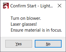
When this setting is enabled, LightBurn will display a text box with a list of items whenever you Start or Send a job to your laser. This is typically used as a reminder of things that need to be done before starting the laser, such as turning on an exhaust fan or putting on protective glasses.
To create a custom checklist, click the Edit button.
Frame Continuously
This setting alters the behavior of the Frame button. When enabled, LightBurn will frame your project repeatedly until stopped, instead of a single time.
Continuous framing is often useful for adjusting material placement within the laser.
Overwrite Files on Device by Default
When enabled, LightBurn will automatically overwrite pre-existing files of the same name when sending a project to your laser's controller. Keep this setting disabled to receive a warning message whenever LightBurn will need to overwrite a file in order to send a new one.
Scanning Offset Adjust
This setting is used to compensate for minor delays in your power supply causing the laser's firing point to be a little behind where it should be when scanning back and forth at high speeds. For more information, please see Scanning Offset Adjustment. For an example of what Scanning Offset problems might look like, please see Troubleshooting: Blurry Edges.
The Add, Delete, Import, and Export buttons allow you to create, edit, import, and export your Scanning Offset settings. You can use this to import settings provided by your machine's manufacturer, share adjustments with other users, or back up your settings before making changes.
Other Options
Not all of these options will be available on all devices. If your device has an option that is not documented here, please reach out to the documentation team using the email link to the right of the headers to let us know.
GCode
Auto-home on Startup
If your laser has homing switches, enable this to automatically home the machine on startup. For lasers without homing switches, disable this setting to prevent GRBL Error 5.
Fast Whitespace Scan
This setting boosts your laser's travel speed through blank areas of an image engraving, if the speed you set here is faster than your laser's engraving speed.
This can save a lot of time if you're engraving an image slowly to get a good burn, particularly if there are large blank areas in the image.
Note
Since Marlin treats G0 and G1 moves identically, this value is used to specify the speed for rapid moves. If you do not set this value, LightBurn will use the same speed as the G1 moves.
Enable $J Jogging
Newer versions of GRBL (1.1 and later) can use this custom jogging mode. $J Jogging, also called Continuous Jogging, has several benefits over normal jogging:
- It does not affect the GCode parser state.
- If soft limits are enabled, jog commands that would go out of bounds are ignored without triggering an error or alarm.
- It allows for cancelling a jog move. After enabling Continuous Jogging in the Move window, hold an arrow key to begin jogging in a direction, and release to stop (cancel) the move.
Enable DTR Signal
This setting controls whether LightBurn sends a Data Terminal Ready signal to the controller to start serial communication. Many programmable hobby-level controllers, including Arduino-based systems, use the DTR pin to reset the controller. LightBurn usually sets this value for you, but if your GCode controller won't communicate, toggling this setting may help.
Enable Laser Fire Button
Enable this setting to add a Fire button and power setting to the Move window to allow you to turn on the laser at low power for focusing, framing, and positioning. When the Fire button is enabled, you can hold the Shift key while framing to enable the beam.
This setting should only be used for diode lasers, which generally don't have a red dot pointer for framing. This should never be used for a CO2 laser, which has an invisble beam that could blind you or start a fire.
Laser On When Framing
This setting turns on the laser at the power level you specify while framing.
Safety Warning
This changes the default behavior of the laser and can cause the laser to fire when a user is not expecting it. Enable this setting with caution, with a very low power level, and only when using a diode laser.
Enable 'Out of Bounds' Warning
Enable this setting to have LightBurn warn you if a job will cause your machine to travel out of bounds. This setting requires that your device has been properly homed and is reporting coordinates correctly, and that your workspace size is set accurately in LightBurn.
Enable GCode Clustering
GCode Clustering condenses the commands sent to your device. For devices that support it, this reduces the bandwidth needed for communication and allows the controller's motion planner to see further ahead. For devices that don't support this feature, enabling it will result in a GRBL error. For more information, please see this post in our forum.
Return to Finish Position
This setting tells LightBurn to send the laser to the specified position after a job is run. This requires that the job is running in Absolute Coords or User Origin mode. Finish position does not work when using Current Position.
Air Assist
This setting determines whether LightBurn uses an M7 or M8 command to enable air assist.
S-value Max
This setting tells LightBurn how to represent 100% power for GRBL and Smoothieware controllers. Current versions of GRBL default to 1000 for this, while older versions use 255. This value needs to match what your controller expects. Read more in GRBL: Low or No Power Output.
Baud Rate
This setting controls the speed at which LightBurn attempts to communicate with your laser's controller.
LightBurn defaults to 115,200 baud for GRBL controllers and 250,000 baud for Marlin controllers. Some Marlin controllers use 115,200 baud, and some GRBL controllers go as low as 9600 baud. If you are having trouble communicating with your controller and are certain the controller and firmware are supported, contact the manufacturer for the correct baud rate for the board, which may be different from the default value.
Transfer Mode
LightBurn defaults to the Buffered transfer mode for communication with GRBL devices. This is faster and more reliable than the Synchronous transfer mode. However, there are a few devices that are incompatible with buffered transfer mode. These devices will stutter, stop, or even restart when buffered communication is selected. If you notice this happening, try switching the transfer mode to Synchronous.
DSP
Start and End Delay
Start Delay allows you to set a delay before the job starts cutting, and End Delay allows you to delay the end of the job after the cut is complete. This is typically used to allow the exhaust fan to start up and spin down.
This feature is only available on Ruida controllers, and only works if the controller's wiring is compatible. Your success in enabling it will be dependent on your specific hardware.
Enable Laser 2 Controls
This setting enables controls for a second laser tube within the same machine. Enable this setting only if your machine has two laser tubes.
Enable Laser 2 Offset
If you are using a dual head laser, use this setting to specify the position of the second laser head relative to the main one.
See Dual Laser Control for more information on dual laser setup.
Increment Filename on Send
This option will automatically increment file names when sending jobs to your laser, to make identifying separate runs easier and maintain your file history. Your file name must contain a digit in order to auto-increment.
Disable Start Button
Use this setting to disable the Start button.
On some lasers, streaming a job with the Start button can be unreliable, so this feature allows you to ensure that all jobs are sent to the laser using the Send button, which transfers the entire job to the laser before it can be started.
Check Bounds When Framing
Enable this setting to have LightBurn check that a job won't travel out of bounds when framing.
Network Timeout
This setting determines how long LightBurn will attempt to communicate with a networked device before reporting a communication failure. Increasing the value from the default of 5000 ms (5 seconds) can help with slower connections.
GCode
The GCode tab contains settings for modifying the job output on GCode devices. For Custom GCode devices, please see Custom GCode.
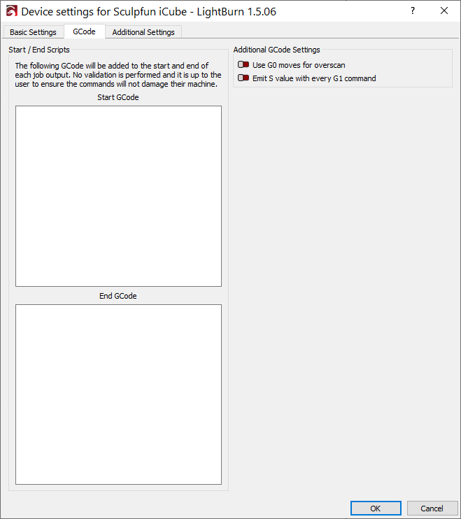
Start / End Scripts
Some devices may need additional commands before or after running a job. GCode entered into these boxes will be added to the start or end of each job LightBurn sends to your device.
Warning
LightBurn does not validate whether these commands are valid or safe. Any modifications here are done at your own risk.
Use G0 Moves for Overscan
Enable this setting to use G0 moves for overscan instead of G1. Some controllers, such as FabCreator Smoothieware boards, have a non-zero power value for their minimum output, causing them to burn during the overscan portion of an engraving. If you find that your laser doesn't shut off completely for overscan moves, try enabling this setting.
Emit S Value With Every G1 Command
Enable this setting to have LightBurn specify the output power of the laser with every move command, rather than only when the power level changes. Enable this setting if your laser does not turn back on after travel moves.
Additional Settings
The Additional Settings tab contains settings used by the Preview simulation engine to calculate the time it will take to complete a job. Changing these settings will not change anything about how the job actually runs, but can make time estimates more accurate.
Use the Read From Controller button to sync these settings with your laser's internal settings, providing much more accurate time estimates without manual adjustment.
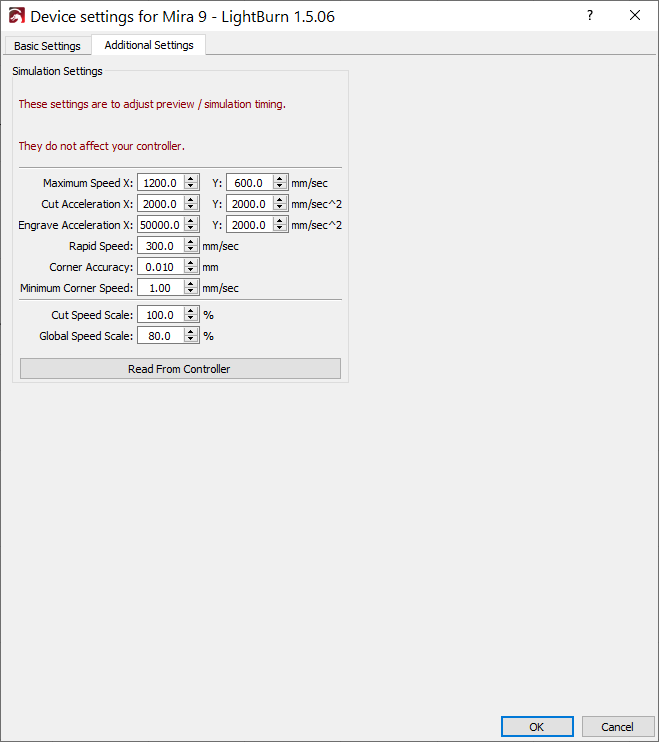
- Maximum Speed X and Y: the maximum speed at which the laser can travel on the X and Y axes, individually.
- Cut Acceleration X and Y: the maximum rate at which the laser can speed up or slow down while cutting (Line operations), on the X and Y axes, individually.
-
Engrave Acceleration: the maximum rate at which the laser can speed up or slow down during engraving (Fill operations), on the X and Y axes, individually.
Note
Y axis Speed and Acceleration values are often set lower than X. Due to the greater mass of the Y axis gantry, many lasers must travel slower in the Y dimension to avoid slipping.
-
Corner Accuracy: a value used to estimate cornering speed. Corner Accuracy is not read from controller. Read more about how this value works for lasers with GRBL controllers here.
- Minimum Corner Speed: the slowest possible speed the laser will turn corners at.
- Cut Speed Scale: scales cut speed estimates by this percentage when simulating job time. Not read from controller. Use this value to manually fine-tune estimates.
- Global Speed Scale: scales all estimates by this percentage when simulating job time. Not read from controller. Use this value to manually fine-tune estimates.
Custom GCode
This tab is only available for devices created using the Custom GCode type. Please see the Custom GCode page for help with it.
