Tutorial: Perfect Image Engrave Settings
Getting an image to engrave well is a task that often stumps even experienced laser-folk. Often images appear too dark, too light, or they appear ‘muddy’ and lack detail.
There are many settings that influence the quality of an engraved image, and each one needs to be refined for the overall image to engrave well, in this article we briefly explain the purpose of these settings and, more importantly, how to get them perfect.
Steps:
1: Focal Length
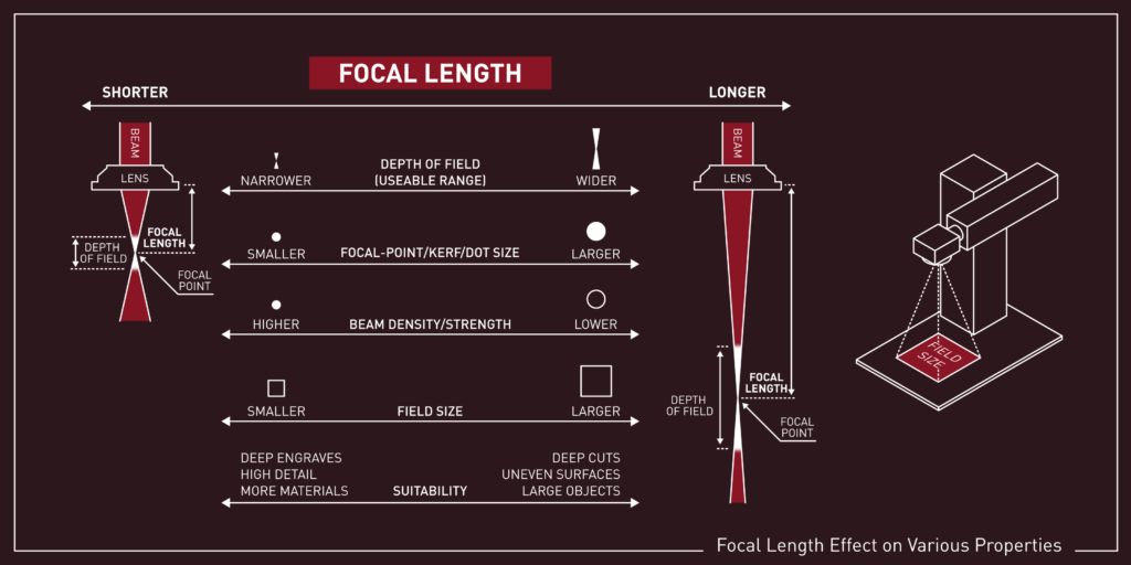
Focal length affects the strength and size of the laser dot where it meets the material. A laser that is perfectly focused will have the smallest dot possible, with the highest strength of the beam.
To find the correct focal length for your hardware, use Laser Tools -> Focus Test for machines with a motorized Z-axis. For those without a motorized Z-axis, use the method of focusing described by your machine’s manufacturer.
Tip
Some people prefer the look of a slightly defocused laser for engraving as it softens the edges between scan lines, however, adjusting settings is easiest with a focused laser. We recommend keeping the laser focused while conducting the following steps, and playing with defocusing as an optional step at the end.
2: Speed & Power
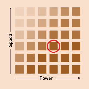
The Speed and Power setting changes the depth and darkness of the engrave.
Use Laser Tools → Material Test with varying speed and power to find a value that engraves nice and dark but doesn’t cut too deep. Dark engraves are generally more difficult with CO2 lasers than diode lasers, but CO2 users will typically have most success with slow speeds and low power.
Apply these speed and power settings to your current layer in Cut Settings Editor.
3: Line Interval/DPI
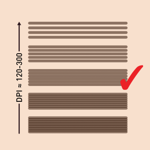
Line Interval and DPI are tied together. They change the distance between each pass (scan) of the laser head. If this setting is too low, images will be very dark (as the lines overlap). Too high and the image will be too light.
Use Laser Tools → Interval Test to find the ideal interval. You’re looking for the value that creates lines that just touch (don’t overlap, nor have gap). Try values between 120 and 300 dpi (0.08-0.2 mm). You will need a microscope or strong magnifying glass.
If you don’t wish to use the interval test, or you are having trouble seeing the overlap of lines on your material, try engraving a gradient and manually varying the line interval in the Cut Settings Editor.
When you have found your settings, save them as the Line Interval for your current layer in Cut Settings Editor.
Tip
- If working with material with a grain (e.g wood), orient the test so the scan lines are perpendicular to the grain, parallel makes it difficult to distinguish between engraving texture and material texture
- A raking light can help to differentiate scan lines.
- For best results create future images with the same DPI as dictated by the line interval you found in this step.
4: Dot Correction
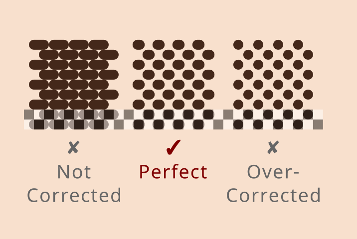
Beams have a thickness which makes dots longer than they should be, which we can correct with Dot Correction. Make sure you adjust your settings in Cut Settings Editor as described below:
- Use the settings for Speed, Power, and Line Interval/DPI you found in the previous steps.
- Set the Image Mode to Ordered.
- Turn off Bi-directional scanning.
- Make sure Negative image is turned off.
Ordered Image Mode on a 50% gray rectangle should produce a checkerboard pattern that is 50% engraved and 50% not. Using a smoother/more organic image mode (e.g. Jarvis) would not produce this consistent pattern. Bidirectional scanning can result in every other layer being slightly offset, unless you've already perfected your Scanning Offset Adjustment table. This doesn't matter for the more organic image modes, but it's very visible in Ordered.
Once you have found the correct Dot Width Correction value, save it in the Cut Settings Editor, switch back to Jarvis Image Mode, and turn Bi-directional scanning back on (it’s a lot quicker). To save yourself a lot of effort in the future, we also recommend making an entry in the Material Library to save your image engraving settings for future use.
5: Adjust Image
Try engraving your image. If you are still not getting the look you desire, it's likely because the image you're using needs some adjusting, which you can do using the Adjust Image tool. Try changing the brightness, contrast, and Gamma, along with the enhance features.
Help & Troubleshooting
If you have any troubles, reach out via the forum or our support email.