Adding Limit Switches to Sculpfun S9 Diode Lasers
This guide shows the steps to install limit switches on a Sculpfun S9 diode laser using off the shelf components, and some laser cut parts. This enables reliable, consistent alignment within the engraving or cutting area with less work for the operator. This guide will be applicable to other diode lasers (such as an AtomStack), especially those using a MKS DLC 2.0 control board and similar.
This enables the use of LightBurn features on these machines, including:
Danger
This guide assumes electrical and mechanical know-how to safely install and enable these features. Please take care to avoid damaging the machine and those around it, including you!
Proceed with caution!
What You'll Need
Some of the materials you'd need (but not neccesarily all) include:
- A compatible diode laser
- 3 Pin Limit Switches
- servo extension cables
- If your cables don't comfortably reach, you may need to purchase or assemble an extension cable yourself.
- Brackets to hold limit switches to your frame (one per limit switch on your frame)
- M3 2020 T-nuts
- M3 Screws
- M3 Hex Driver
- 2020 Extrusion Cover
- Scissors (to cut said extrusion cover)
- Zip Ties (to fasten the limit switch cables)
If you'd like to create custom cables rather than use a servo extension cable, here are the ones we used.
Limit Switches
Limit switches are small, electro-mechanical devices that when depressed, create a pathway for a signal to pass through. We can use them to tell the laser's controller that we've reached the end of their motion.

In this guide, we'll be using a 3 wire style limit switch, mounted to a printed circuit board to make installing it on your machine easier.
Limit Switch Cabling
These cables are responsible for passing the signal back to your laser, and through checks are required to connect them correctly. If the cable is too short, it can damage the connector, damage your diode laser, or other components.
Before Disassembly
If you intend to use the laser cut brackets for the limit switches, you'll want to cut those before disassembling your laser for installation.
Cutting Out Brackets
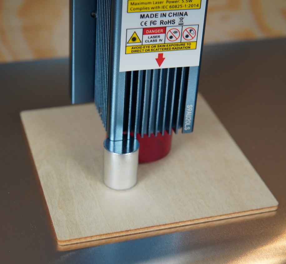
Same as with standard use of your laser, you'll want to focus the head relative to the cutting material, in our case, some thin 3 mm wood.
Document Setup
Use the LightBurn preview window to ensure that your document as set up looks good. The default settings for the S9 should be adequate. We used:
250mm/m
100% Power Max (%)
Pass Count: 2
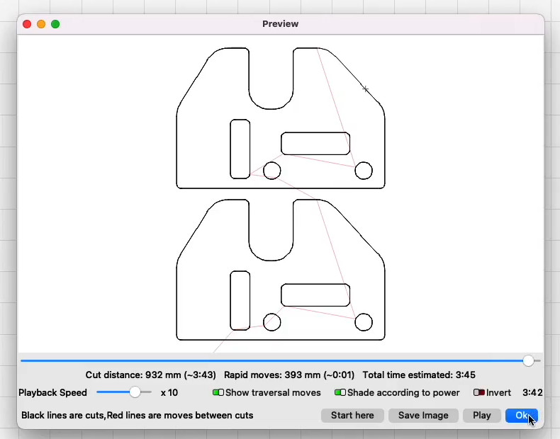
You may want to use the "Square Frame" command within LightBurn to ensure the material you're engraving has the sufficient area to cut out the brackets.
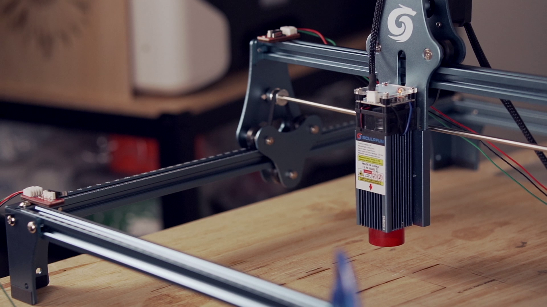
Mechanical Installation
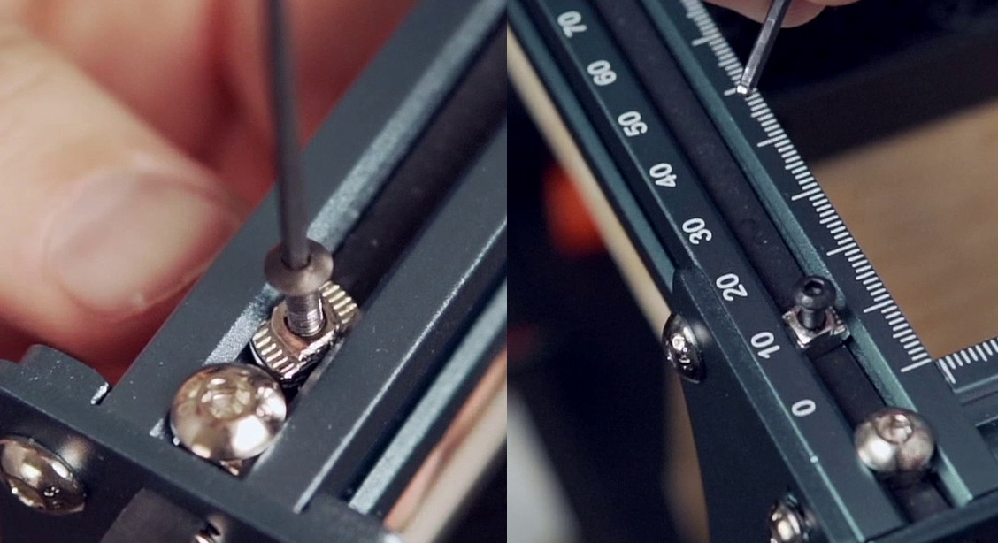
To install the limit switches, you'll need to insert an M3 2020 t-nut into the frame sideways, and then rotate it 90° in the frame slot to align correctly for retention. You may need other tools to insert & rotate them appropriately; we found that a small flat-bladed screwdriver may be helpful.
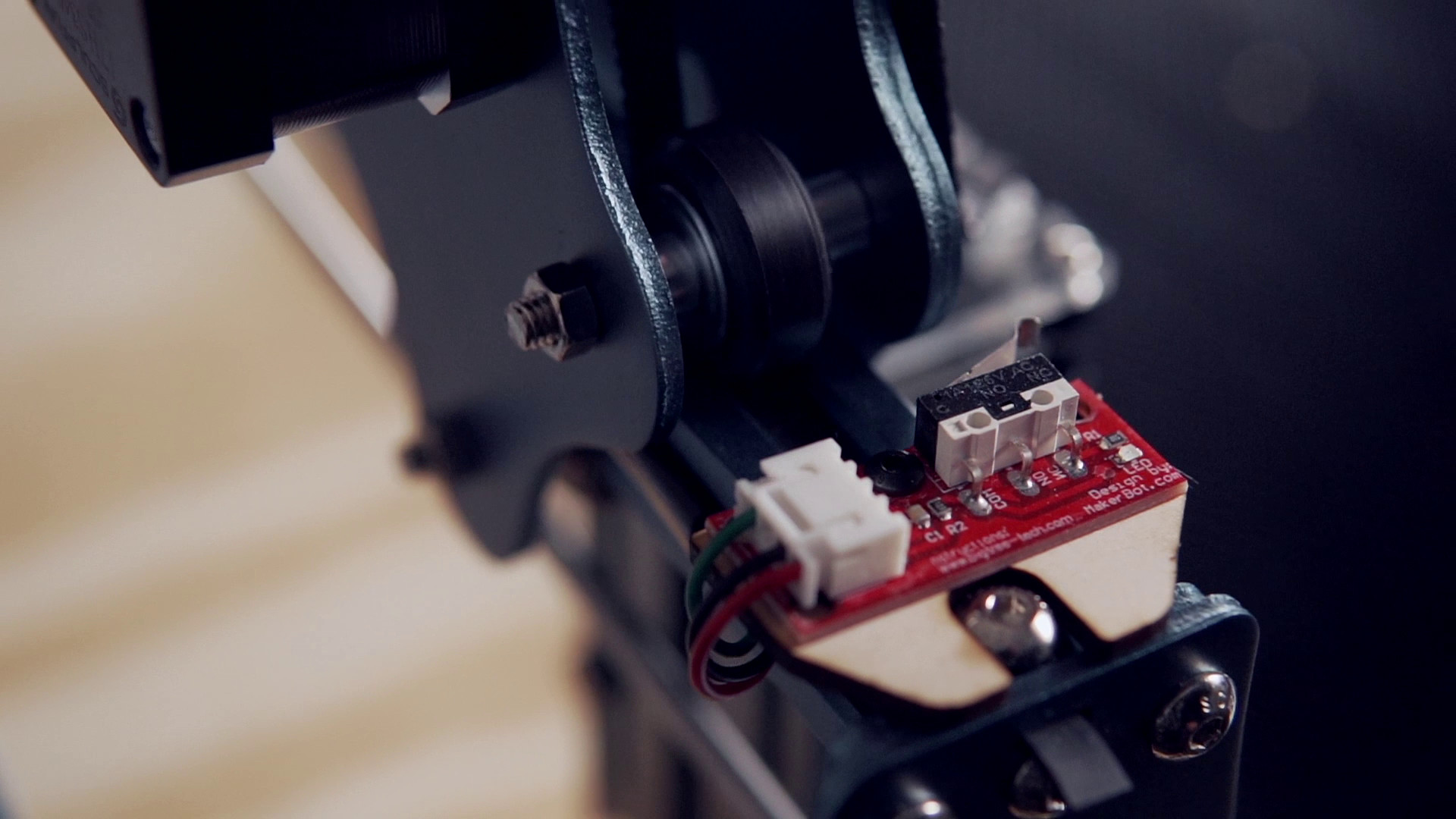
When mounting the limit switch, place the cut or printed spacer underneath the limit switch board, and oriented it such that the "arm" of the limit switch faces the head of the laser.
Here we use a M3 x 8 mm screw to fasten the board to the frame.
This process should be repeated such that a limit switch is positioned for both the X and Y axes of the machine.
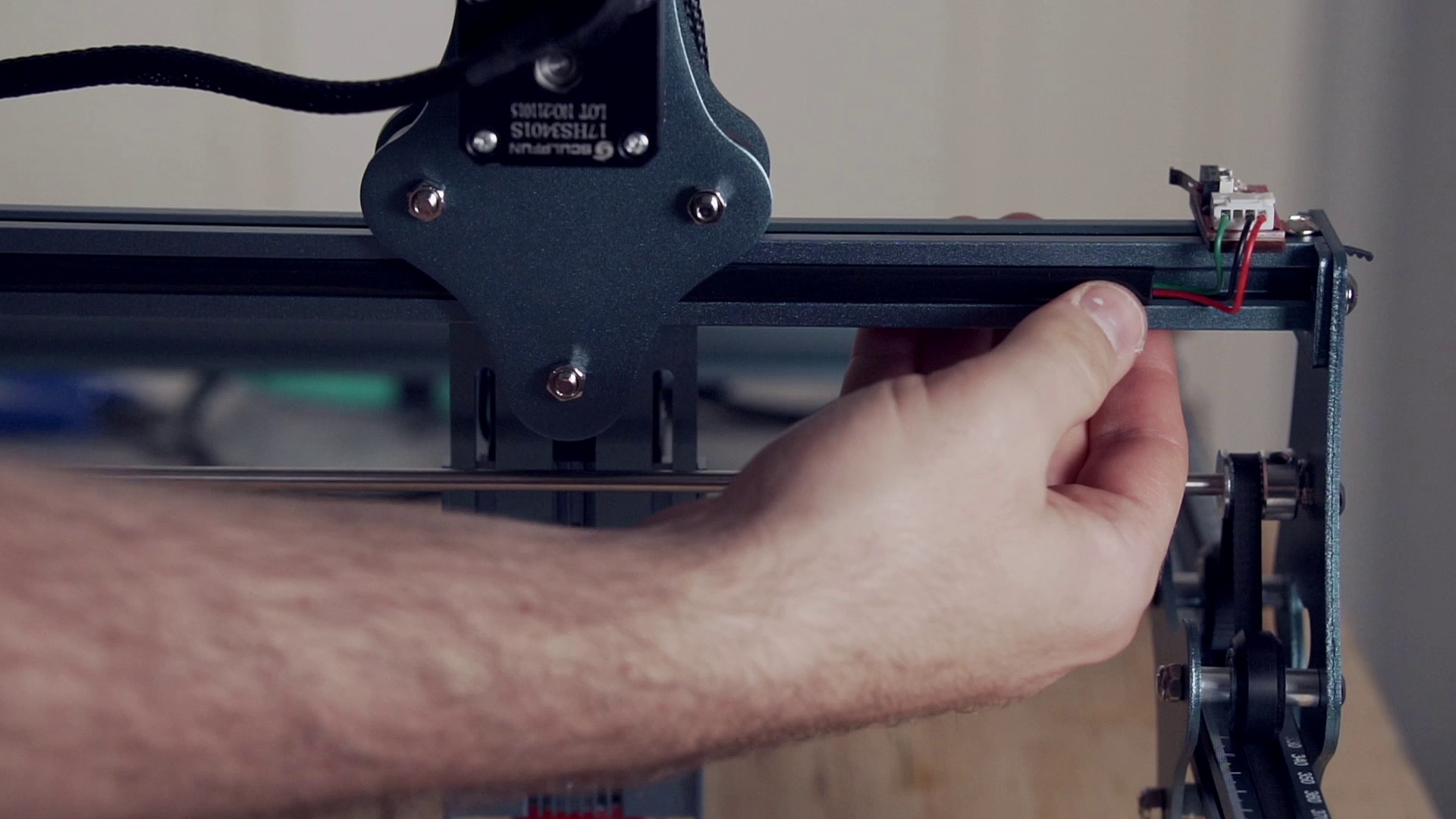
Wiring
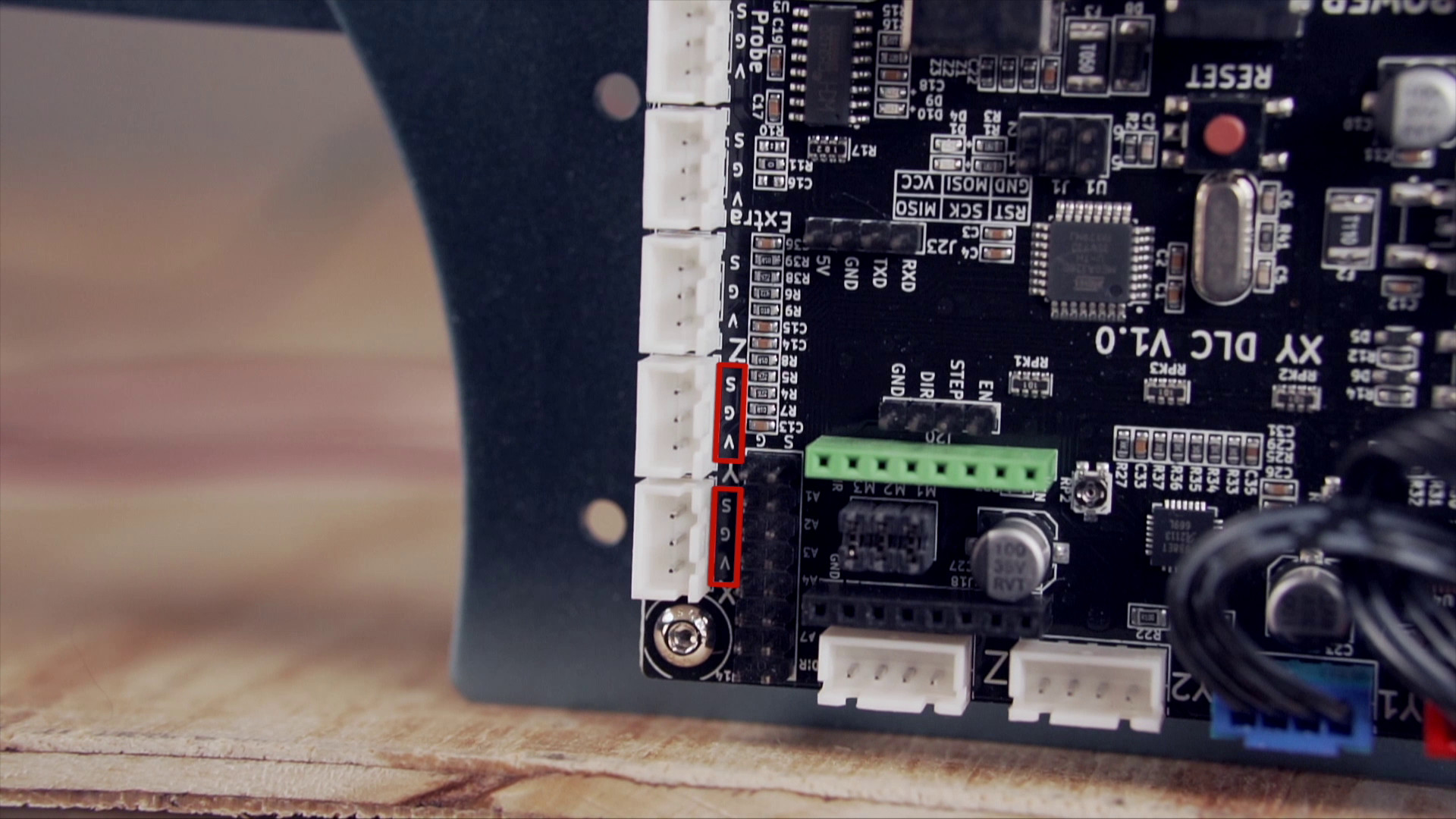
Our limit switches are labeled as having three pins for use:
- G - Ground
- V - Voltage
- S - Signal
This labeling also applies to the printed circuit board that has the control electronics of the laser. Be sure to match each axis' limit switch to the correct connector and direction, for X or Y axis as is correct.
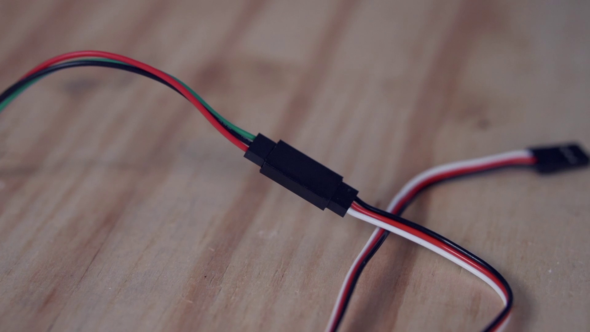
Notes on Extensions
The cables we're using, while they technically fit, aren't what's intended on these connectors. We suggest you use a crimper and make a custom cable, but we understand this isn't possible for everyone and opted to include this as a more accessible option.
The preferred way would have the user crimp JST connections on a single length of cable per axis and make it exactly to length, but we recognize this isn't always an option.
Danger
Please be aware that use of "PWM" style connectors in a JST housing permits the inversion of the connection, potentially damaging your laser. Ensure the pins are connected with the correct labels (i.e. ground to ground, signal to signal, etc.) before turning on your laser on.
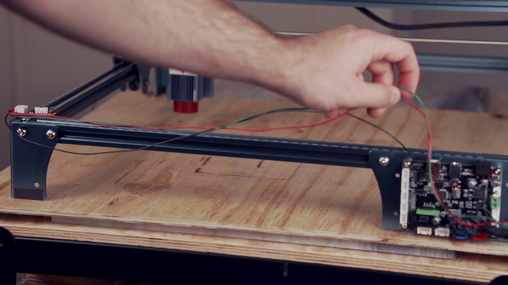
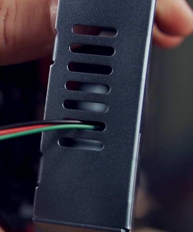
When continuing to hook up the wiring, you'll likely want to route the extensions or connections through the pre-existing hole in the housing, or through the vent holes on the side. This ensures you can re-close the housing and protect your electronics.
Next you'll need to test the machine while opened up. This allows you to resolve those issues you might encounter more easily. Carefully reconnect power and USB to the device, and turn it back on.
The diode laser won't immediately understand how to use the limit switches, and as such, we'll need to do software configuration within LightBurn.
Software
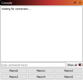
The first major check is to ensure that upon re-powering the device, LightBurn can still see your laser; confirm this through the Console dock. If so, you'll need to use the following codes to enable limit switch homing.
$22=1
Danger
Be ready to power off the machine in the event it does something unintended and dangerous.
This GRBL command enables limit-switch based homing. To test your homing behavior, click the "Home" button in LightBurn in the "Laser" window.
If your device attempts to home in the wrong direction, you may need to change the "homing location" via more GRBL commands.
For ours, we needed to do $23=3 to chose the near, left side as our 'home' location. If your device has the limit switches in another location, you'll want to reference this guide as to what the different values mean with respect to limit switch "bitmasks".
Homing Speed
By default, our device was rather slow during the homing process, and we changed the following to allow it to home more quickly.
$25=8000 (homing speed)
$24=100 (re-seek speed)
The final configuration information needed are for the workspace offset, which we can find by looking in the "Move" window when clicking "Get Position".
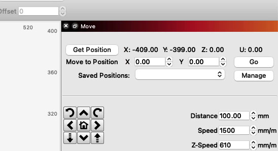
Taking these values, go back to the "Console" tab and enter the following GCode command:
G10 L2 P1 X-409 Y-399
These values directly use the data observed just prior, with the L2 P1 portion indicating to the device the specific offset mode (corrent workspace offsets to the specified values) and P1 to the "tool number" (value of 1, the first and only present on this machine).
We'll also need to tell the machine's status reporting to be relative to the workspace origin, and we can do that with:
$10=0
Stock Firmware Warning
Many devices don't actually have GRBL firmware that by default stores these values in the memory of the laser's controller. As such, rebooting would wipe these values out, reverting the work you've done.
The best fix is to re-flash the firmware. We have a guide on how to do this with the Sculpfun S9. However, you should always check your manufacturer's directions for this process as it varies between devices and can change as manufacturers make updates.
If re-flashing the firmware isn't an option right now, you can use the Macros button under the Console window.
By right-clicking the button, we can re-name it, and combine all of our commands together for use, which might look something like this:
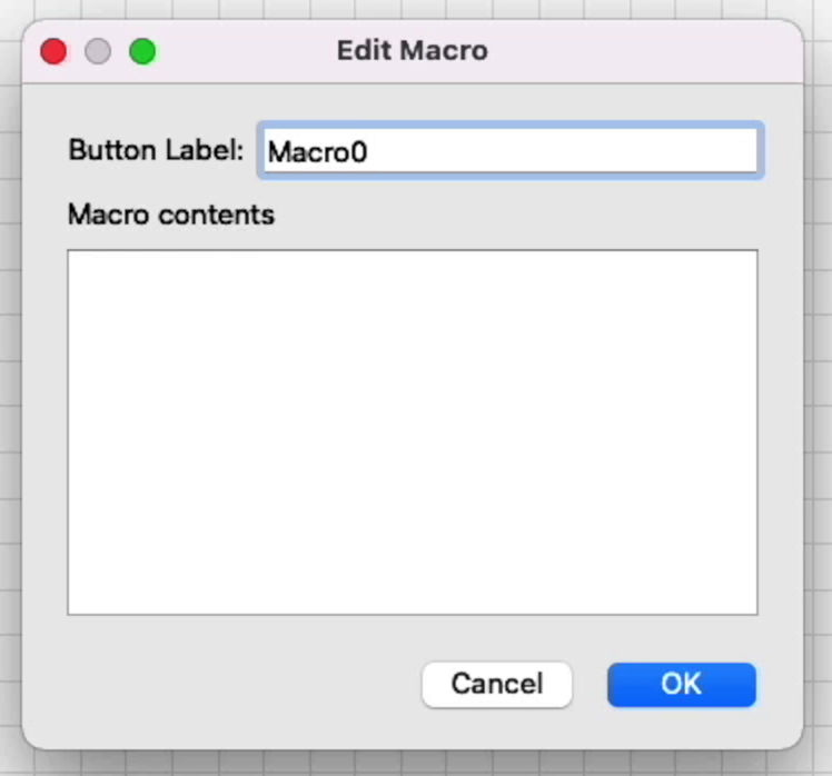
If you'd like to copy this behavior and simply use it as-is, still verify your G10 command has the correct offsets.
$22=1
$23=3
$25=8000
$24=100
G10 L2 P1 X-409 Y-399
$10=0
Reassembly
Once we've confirmed that this configuration works correctly, we can begin to reassemble our housing and more permanently install the wires for the limit switches. Turn the machine off to do so, to avoid any errant connections of the case to the electronics resulting in a short.
You can use 2020 extrusion covers cut to size to protect and hide the wires inside the grooves of the extrusion frame, and zip-tie the limit switch cable for the gantry to the pre-existing cable to the diode head itself.