Custom GCode
Custom GCode is a new GCode device type added in LightBurn 1.5 to allow you to customize the way LightBurn generates the commands used to drive your laser.
Understanding Custom GCode
Updates in LightBurn 1.7
Starting in LightBurn 1.7, Custom GCode devices automatically track and restore modal GCode states for units (G20 and G21) and movement (G90 and G91).
To understand Custom GCode, you'll need to know a bit about GCode and how it's generated.
GCode is a set of commands that breaks down what you want a machine to do into a series of simple steps. For instance, G0 X10 means "do a rapid move 10 units in the positive x direction", and G4 P10 means "pause for 10 seconds". LightBurn takes your designs and generates GCode to tell your machine how to produce those designs. You can see this for yourself by drawing something in LightBurn, clicking the Save GCode button in the Laser window, saving the file, and opening it in a text editor.
This gets a little more complex when dealing with a variety of different machines. Different machines will expect GCode to be formatted slightly differently. For instance, turning on your laser is M3 in older versions of GRBL, M4 for Smoothie boards and newer GRBL versions, M106 S{power} in Marlin, and M67 E0 Q{power} in LinuxCNC. The device types built into LightBurn cover a wide range of common machines, but Custom GCode extends that even further by allowing you to specify custom formats.
Configuring Custom GCode
To create a custom GCode template, you need to create a device of the Custom GCode type and go to Device Setting.
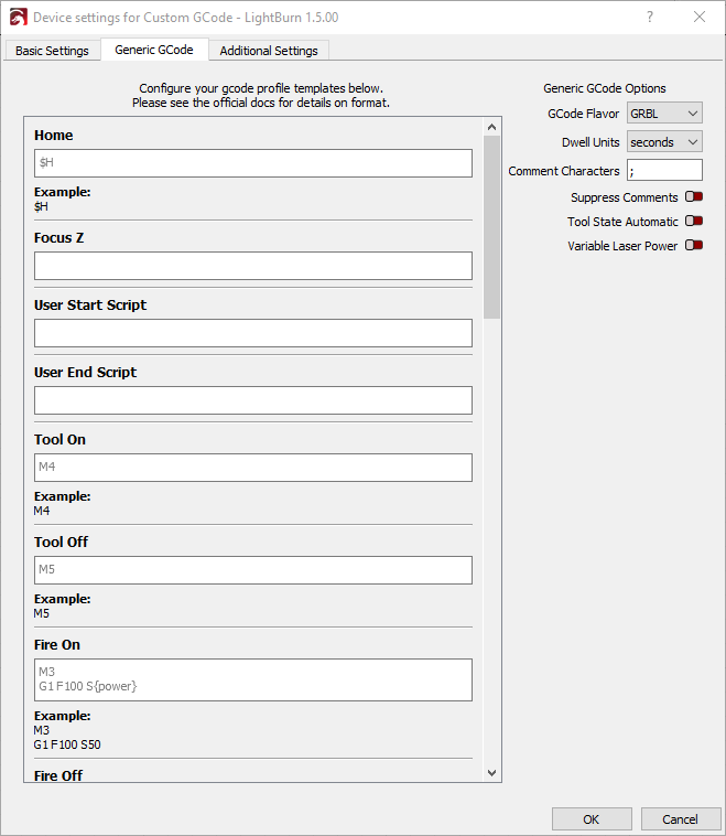
Custom GCode Options
In this section, you can set some baseline options for your custom GCode profile.
- GCode Flavor: What flavor of GCode to use as a base
- Dwell Units: Whether pause times are given in seconds or milliseconds
- Comment Characters: What character(s) are used to indicate comments
- Suppress Comments: Enabling this will strip all comments from the GCode LightBurn generates
- Tool State Automatic: Enabling this will cause the tool to automatically turn on during a cut move
- Variable Laser Power: Enabling this will allow you to control the laser's power beyond on and off
GCode Commands
This section lists each command that can be customized. Using Cut Move as an example:
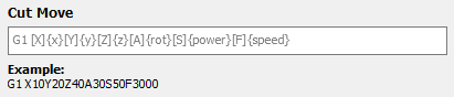
- The title indicates what command you're working with
- The text box contains the default value in gray text, if there is a default. If there is no default value, the text box is blank.
- Below the text box is a preview of what the output for the command would look like, based on current settings.
Hover over a section for more detailed information.
Custom GCode Variables
These variables can be used in your GCode templates
| Variable | Description | MillMage Only (will be removed from LB version of page) |
|---|---|---|
x | X axis position | |
y | Y axis position | |
z | Z axis position | |
r, a, u, rot, rotation | Rotary axis position | |
x_probe | X probe offset | yes |
y_probe | Y probe offset | yes |
z_probe | Z probe offset | yes |
s, speed | Movement speed | |
feed, feedrate | Movement speed | yes |
p, power | Laser Power | |
rpms, spindlespeed | Spindle speed or RPM/s | yes |
dwell | Dwell time | |
tool | Tool number |
Custom GCode Macros
Relative and absolute mode are controlled by LightBurn, so if you need to change it within your GCode template, use the following macros to prevent LightBurn overriding your changes. You must always use |RESTORE| when you're done to ensure a return to the previous mode.
| Macro | Description |
|---|---|
|REL| | Enter relative mode |
|ABS| | Enter absolute mode |
|RESTORE| | Restore previous mode |
Optional And Required Values
Surrounding the letter before a variable with [] will tell LightBurn that this portion of the command has not changed since the last emit. Putting a * in front of any variable will tell LightBurn to skip the entire line if it has not been changed.
G1 X{x} Y{y} Z{z}will always output the X, Y, and Z values.G1 [X]{x} [Y]{y} [Z]{z}will skip any values that have not changed.M106 S{*power}this will output theM106command only if it has been changed.
As an example, let's look at GCode commanding the tool to move along a rectangular path.
Using G1 X{x} Y{y} Z{z}, you might see something like:
G1 X0 Y0 Z0
G1 X100 Y0 Z0
G1 X100 Y50 Z0
G1 X0 Y50 Z0
G1 X0 Y0 Z0
On the other hand, using G1 [X]{x} [Y]{y} [Z]{z}, the same rectangle would look something like:
G1 X0 Y0 Z0
G1 X100
G1 Y50
G1 X0
G1 Y0
Non-Printable / Non-Typeable Characters
Control characters can be output by using \x followed by the two digit hex value of the character. For instance, \x18 represents an immediate job abort on a GRBL device.